Nissan Versa (N17): P1225 TP sensor
DTC Logic
DTC DETECTION LOGIC
| DTC No. | Trouble diagnosis | DTC detecting condition | Possible cause |
| P1225 | Closed throttle position learning performance | Closed throttle position learning value is excessively low. | Electric throttle control actuator (TP sensor 1 and 2) |
DTC CONFIRMATION PROCEDURE
1.PRECONDITIONING
If DTC Confirmation Procedure has been previously conducted, always perform the following procedure before conducting the next test.
- Turn ignition switch OFF and wait at least 10 seconds.
- Turn ignition switch ON.
- Turn ignition switch OFF and wait at least 10 seconds.
TESTING CONDITION: Before performing the following procedure, confirm that battery voltage is more than 10 V at idle.
>> GO TO 2.
2.PERFORM DTC CONFIRMATION PROCEDURE
- Turn ignition switch ON.
- Turn ignition switch OFF and wait at least 10 seconds.
- Turn ignition switch ON.
Check 1st trip DTC.
Is 1st trip DTC detected?
YES >> Go to EC, "Diagnosis Procedure".
NO >> INSPECTION END
Diagnosis Procedure
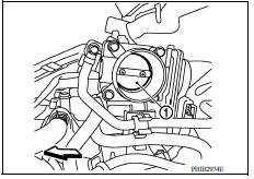
1.CHECK ELECTRIC THROTTLE CONTROL ACTUATOR VISUALLY
- Turn ignition switch OFF.
- Remove the intake air duct. Refer to EM, "Removal and Installation".
- Check if foreign matter is caught between the throttle valve (1) and the housing.
: Vehicle front
Is the inspection result normal?
YES >> GO TO 2.
NO >> Remove the foreign matter and clean the electric throttle control actuator inside, and then perform throttle valve closed position learning. Refer to EC, "Work Procedure".
2.REPLACE ELECTRIC THROTTLE CONTROL ACTUATOR
Replace electric throttle control actuator. Refer to EM, "Removal and Installation".
>> INSPECTION END
 P1217 engine over temperature
Other materials:
ABS Actuator and electric unit
(control unit)
Exploded View
1. ABS actuator and electric unit (control
unit)
2. ABS actuator and electric unit (control
unit) harness connector
3. Bushing
4. Bracket A. To master cylinder secondary side B. To master cylinder primary
side
C. To front wheel cylinder (LH) D. To rear wheel cylinder (RH ...
Door check link
DOOR CHECK LINK : Removal and Installation
REMOVAL
Fully close the front door window.
Remove front door finisher. Refer to INT "Removal and Installation".
Remove front door speaker bolts.
Disconnect harness connector from front door speaker and remove.
Remove door check link ...
Categories
- Manuals Home
- Nissan Versa Owners Manual
- Nissan Versa Service Manual
- Video Guides
- Questions & Answers
- External Resources
- Latest Updates
- Most Popular
- Sitemap
- Search the site
- Privacy Policy
- Contact Us

0.0058