Nissan Versa (N17): Diagnosis system (audio unit)
Description
The audio unit on board diagnosis performs the functions listed in the table below:
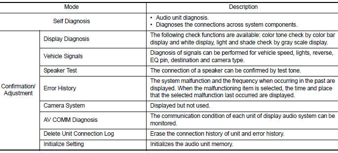
On Board Diagnosis Function
METHOD OF STARTING
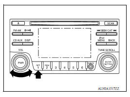
1. Turn the ignition ON.
2. Turn the audio system OFF.
3. While pressing the preset 1 button, turn the volume control dial clockwise or counterclockwise for 40 clicks or more. Shifting from current screen to previous screen is performed by pressing BACK button.
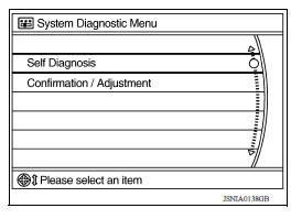
4. The trouble diagnosis initial screen is displayed, and Self Diagnosis or Confirmation/Adjustment can be selected.
SELF DIAGNOSIS MODE
Audio Unit Self Diagnosis
1. Select Self Diagnosis.
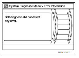
2. Self diagnosis screen is displayed. The bar graph visible in center of screen indicates progress of self diagnosis.
3. Diagnosis results are displayed after the self diagnosis is completed.
The unit names and the connection lines are color coded according to the diagnostic results.
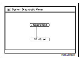
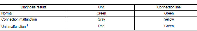
1: Control unit (audio unit) is displayed in red.
- Replace audio unit if Self Diagnosis did not run because control unit malfunction is indicated. The symptom is audio unit internal error. Refer to AV "Removal and Installation".
- If multiple errors occur at the same time for a single unit, the screen switch colors are determined according to the following order of priority: red > gray.
4. Comments of self diagnosis results can be viewed in the diagnosis result screen.
Audio Unit Self Diagnosis Results
|
Only Unit Part Is Displayed In Red |
||
| Screen switch | Description | Possible cause |
| Control unit | Malfunction is detected in audio unit power supply and ground circuits. | - Audio unit power supply or ground circuits.
Refer to AV "AUDIO UNIT : Diagnosis Procedure". - If no malfunction is detected in audio unit power supply and ground circuits, replace audio unit. Refer to AV "Removal and Installation". |
| A Connecting Cable Between Units Is Displayed In Yellow | ||
| Area with yellow connection lines | Description | Possible cause |
| Control unit ⇔ BT HF Unit | When one of the following is detected: - malfunction is detected in Bluetooth control unit power supply and ground circuits. - malfunction is detected in AV communication circuits between audio unit and Bluetooth control unit. |
- Bluetooth control unit power supply or
ground circuits.
Refer to AV "BLUETOOTH CONTROL UNIT : Diagnosis Procedure". - AV communication circuits between audio unit and Bluetooth control unit. |
Audio Unit Confirmation/Adjustment
1. Select Confirmation/Adjustment.
2. Select each switch on the Confirmation/Adjustment screen to display the relevant trouble diagnosis screen. Press the BACK switch to return to the initial Confirmation/Adjustment screen.
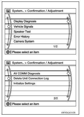
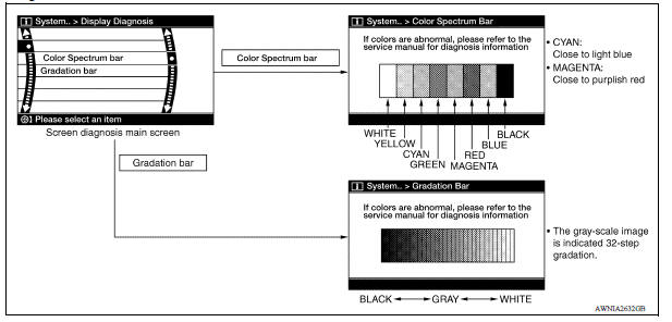
Display Diagnosis
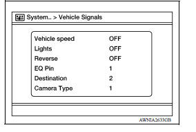
Vehicle Signals
A comparison check can be made of each actual vehicle signal and the signals recognized by the system.
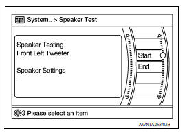
Speaker Test
Select Speaker Test to display the Speaker Diagnosis screen. Press Start to generate a test tone in a speaker. Press Start again to generate a test tone in the next speaker. Press End to stop the test tones.
Error History
The self diagnosis results are judged depending on whether any error occurs from when Self Diagnosis is selected until the self diagnosis results are displayed.
However, the diagnosis results are judged normal if an error has occurred before the ignition switch is turned ON and then no error has occurred until the self diagnosis start. Check the Error Record to detect any error that may have occurred before the self diagnosis start because of this situation.
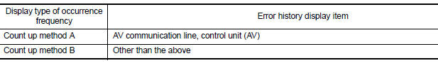
The frequency of occurrence is displayed in a count up manner. The actual count up method differs depending on the error item.
Count up method A
- The counter is set to 40 if an error occurs. 1 is subtracted from the counter if the condition is normal at a next ignition ON cycle.
- The counter lower limit is 1. The counter can be reset (no error record display) with the Delete log switch.
Count up method B
- The counter increases by 1 if an error occurs when ignition switch is ON. The counter will not decrease even if the condition is normal at the next ignition ON cycle.
- The counter upper limit is 50. Any counts exceeding 50 are ignored. The
counter can be reset (no error
record display) with the Delete log switch.
Error item
Some error items may be displayed simultaneously according to the cause. If some error items are displayed simultaneously, the detection of the cause can be performed by the combination of display items
| Error item | Description | Possible cause |
| CONTROL UNIT (AV) | AV communication circuit initial diagnosis malfunction is detected. | Replace the audio unit if the malfunction
occurs constantly.
Refer to AV "Removal and Installation" |
| AV COMM CIRCUIT | When one of the following is detected: - malfunction is detected in Bluetooth control unit power supply and ground circuits. - malfunction is detected in AV communication circuits between audio unit and Bluetooth control unit. |
- Bluetooth control unit power supply or
ground circuits.
Refer to AV "BLUETOOTH CONTROL UNIT : Diagnosis Procedure". - AV communication circuits between audio unit and Bluetooth control unit. |
AV COMM Diagnosis
- Displays the communication status between audio unit (master unit) and Bluetooth control unit.
- The error counter displays OK if any malfunction was not detected
in the past and displays 0 if a malfunction is detected. It increases
by 1 if the condition is normal at the next ignition switch ON cycle.
The upper limit of the counter is 39.
- The error counter is erased if Reset is pressed.
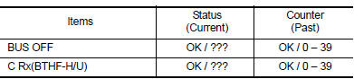
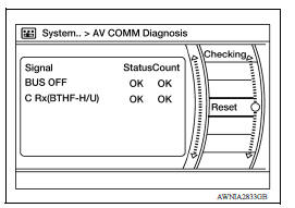
NOTE: "???" indicates UNKWN.
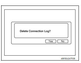
Delete Unit Connection Log
Deletes any unit connection records and error records from the audio unit memory (clears the records of the unit that has been removed).
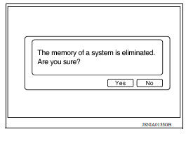
Initialize Settings
Deletes data stored from the audio unit.
 System
System Diagram System Description AUDIO SYSTEM The audio system consists of the following components Audio unit Front door speakers Rear door speakers Steering wheel audio control s ...
Diagnosis system (bluetooth control
unit)
Diagnosis Description The Bluetooth control unit has two diagnostic checks. The first diagnostic check is performed automatically every ignition cycle during control unit initialization. The sec ...
Other materials:
Cold weather driving
Freeing a frozen door lock
To prevent a door lock from freezing, apply deicer
through the key hole. If the lock becomes
frozen, heat the key before inserting it into the key
hole, or use the remote keyless entry key fob or
the NISSAN Intelligent Key.
Antifreeze
In the winter when it is antic ...
SRS Air bag warning lamp does not
turn on
AIR BAG Warning Lamp Does Not Turn On
1.CHECK METER FUSE
Check the 10A fuse [No. 3, located in the fuse block (J/B)].
Is the fuse blown?
YES >> GO TO 2
NO >> GO TO 3
2.REPLACE METER FUSE AND CHECK AGAIN
Replace 10A fuse [No. 3, located in the fuse block (J/B)] and turn ignition
...
Categories
- Manuals Home
- Nissan Versa Owners Manual
- Nissan Versa Service Manual
- Video Guides
- Questions & Answers
- External Resources
- Latest Updates
- Most Popular
- Sitemap
- Search the site
- Privacy Policy
- Contact Us

0.0063