Nissan Versa (N17): B26F1 Ignition relay
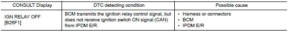
DTC Logic
DTC DETECTION LOGIC
DTC CONFIRMATION PROCEDURE
1.PERFORM DTC CONFIRMATION PROCEDURE
1. Turn ignition switch ON, and wait for 2 seconds or more.
2. Check "Self-diagnosis result" with CONSULT.
Is DTC detected?
YES >> Go to PCS "Diagnosis Procedure".
NO >> Inspection End.
Diagnosis Procedure
Regarding Wiring Diagram information, refer to PCS "Wiring Diagram".
1.CHECK IPDM E/R SELF-DIAGNOSTIC RESULT
1. Turn ignition switch ON.
2. Erase the DTC of IPDM E/R.
3. Turn ignition switch OFF.
4. Turn ignition switch ON and check the DTC again.
Is DTC detected?
YES >> Repair or replace the malfunctioning part. Refer to BCS "DTC Index".
NO >> GO TO 2.
2.CHECK IGNITION RELAY-1 CONTROL SIGNAL (IPDM E/R)
Check voltage between BCM harness connector and ground.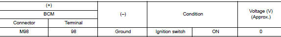
Is the inspection result normal?
YES >> GO TO 3.
NO >> Replace BCM. Refer to BCS "Removal and Installation".
3.CHECK IGNITION RELAY-1 CONTROL SIGNAL CIRCUIT (IPDM E/R)
1. Turn ignition switch OFF.
2. Disconnect BCM and IPDM E/R connectors.
3. Check continuity between BCM harness connector and IPDM E/R harness
connector.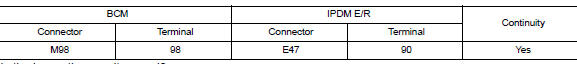
Is the inspection result normal?
YES >> Replace IPDM E/R.
NO >> Repair or replace harness.
 B261A Push-button ignition switch
Other materials:
Compressor does not operate
Description
SYMPTOM
Compressor does not operate.
Diagnosis Procedure
NOTE:
Perform self-diagnosis with CONSULT before performing symptom
diagnosis. If any malfunction result or
DTC is detected, perform the corresponding diagnosis.
Check that refrigerant system is fully charged. If t ...
Rear seat
Exploded View - Fixed Seatback
FIXED SEATBACK
1. Headrest holder (locked) 2. Headrest holder (free) 3. Rear seatback
assembly
4. Seatback trim 5. Seatback pad 6. LATCH bracket (RH)
7. Seat cushion assembly 8. Seat cushion trim 9. Seat cushion pad
10. Seat cushion hook 11. LATCH bracket (L ...
Categories
- Manuals Home
- Nissan Versa Owners Manual
- Nissan Versa Service Manual
- Video Guides
- Questions & Answers
- External Resources
- Latest Updates
- Most Popular
- Sitemap
- Search the site
- Privacy Policy
- Contact Us

0.0058