Nissan Versa (N17): B26F6 BCM
DTC Logic
DTC DETECTION LOGIC
NOTE:
- If DTC B26F6 is displayed with DTC U1000, first perform the trouble diagnosis for DTC U1000. Refer to PCS "DTC Logic".
- If DTC B26F6 is displayed with DTC U1010, first perform the trouble
diagnosis for DTC U1010. Refer to
PCS "DTC Logic".

DTC CONFIRMATION PROCEDURE
1.PERFORM DTC CONFIRMATION PROCEDURE
1. Turn ignition switch ON, and wait for 0.5 seconds or more.
2. Check "Self-diagnosis result" of BCM with CONSULT.
Is DTC detected?
YES >> Go to PCS "Diagnosis Procedure".
NO >> Inspection End.
Diagnosis Procedure
Regarding Wiring Diagram information, refer to PCS "Wiring Diagram".
1. CHECK SELF DIAGNOSTIC RESULT FOR IPDM E/R
Perform self diagnostic result for IPDM E/R.
Are any DTCs detected?
YES >> Refer to PCS"DTC Index".
NO >> GO TO 2
2. CHECK IGNITION RELAY-1 POWER SUPPLY (IPDM E/R)
Check voltage between IPDM E/R connector E47 terminal 90 and ground.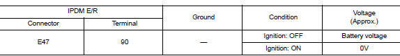
Is the inspection result normal?
YES >> Replace IPDM E/R. Refer to PCS "Removal and Installation".
NO >> GO TO 3.
3. CHECK IGNITION RELAY-1 POWER SUPPLY (BCM)
Check voltage between BCM connector M98 terminal 98 and ground.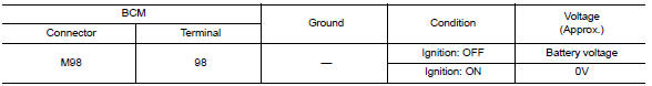
Is the inspection result normal?
YES >> Refer to GI "Intermittent Incident".
NO >> Replace BCM. Refer to BCS "Removal and Installation".
 B26F2 Ignition relay
Other materials:
Control panel buttons - color screen with Navigation System (if so equipped)
WARNING
Positioning of the heating or air conditioning
controls and display controls
should not be done while driving in order
that full attention may be given to
the driving operation.
Do not disassemble or modify this system.
If you do, it may result in accidents,
fire, or elec ...
Brakes
If the brakes do not operate properly, have the
brakes checked. It is recommended that you visit
a NISSAN dealer for this service.
Self-adjusting brakes
Your vehicle is equipped with self-adjusting
brakes.
The front disc-type brakes self-adjust every time
the brake pedal is applied. The rea ...
Categories
- Manuals Home
- Nissan Versa Owners Manual
- Nissan Versa Service Manual
- Video Guides
- Questions & Answers
- External Resources
- Latest Updates
- Most Popular
- Sitemap
- Search the site
- Privacy Policy
- Contact Us

0.0053