Nissan Versa (N17): EPS control unit
Reference Value
VALUES ON THE DIAGNOSIS TOOL
CAUTION: The output signal indicates the EPS control unit calculation data. The normal values will be displayed even in the event that the output circuit (harness) is open.
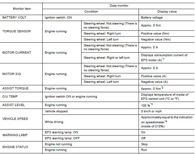
*1: Almost in accordance with the value of "MOTOR SIG". It is not a malfunction though these values are not accorded when steering quickly.
*2: A fixed value is indicated regardless of steering turning.
*3: Normally displays 100%. In case of an excessive stationary steering, the assist curvature gradually falls.
However, it returns to 100% when left standing.
*4: It is not a malfunction, though it might not be corresponding just after ignition switch in turned ON.
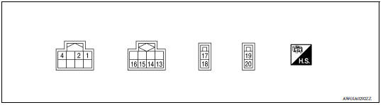
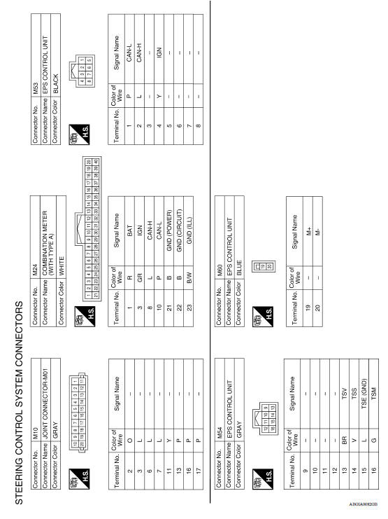
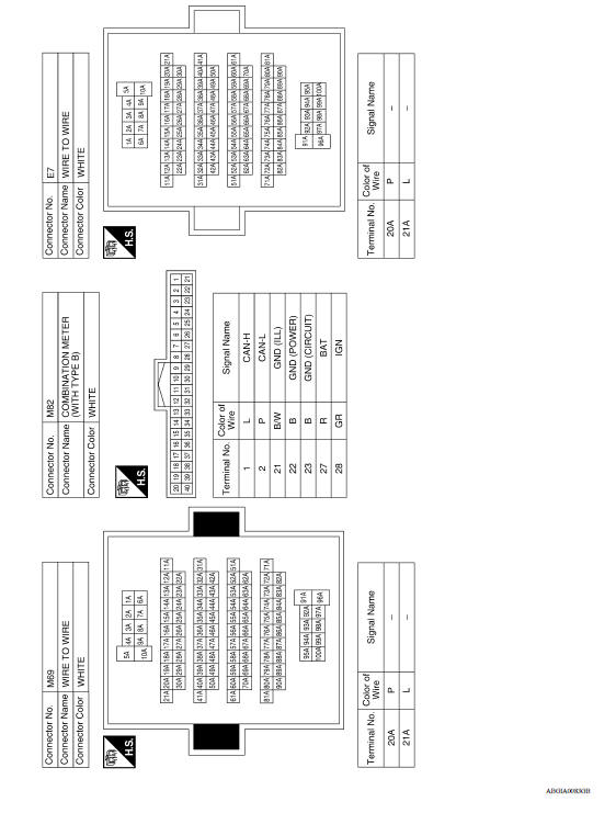
TERMINAL LAYOUT
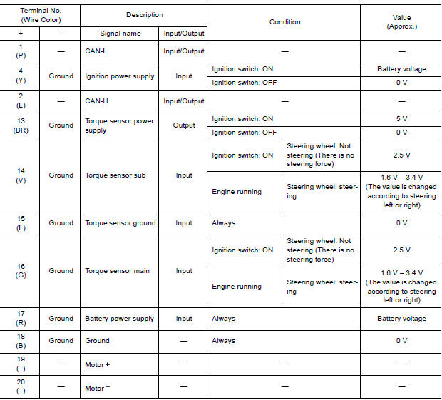
PHYSICAL VALUES
Fail-Safe
- If any malfunction occurs in the system and control unit detects the malfunction, EPS warning lamp on combination meter turns ON to indicate system malfunction.
- When EPS warning lamp is ON, the system enters into a manual steering state. (Steering wheel turning force becomes heavy.)
- Under abnormal vehicle speed signal conditions, vehicle speed is judged as constant.
Protection Function
EPS control unit decreases the output signal to EPS motor while extremely using the power steering function (e.g., full steering) consecutively for protecting EPS motor and EPS control unit (Overload protection control).
While activating overload protection control, the assist torque gradually decreases, and the steering wheel turning force becomes heavy. The normal assist torque reactivates by no steering.
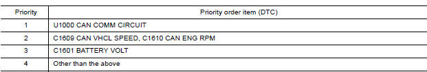
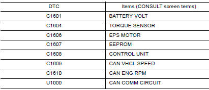
DTC Inspection Priority Chart
When multiple DTCs are detected simultaneously, check one by one depending on the following priority list.
DTC Index
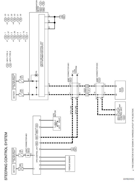
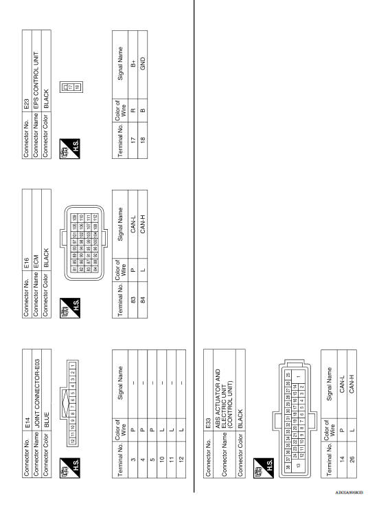
WIRING DIAGRAM
ELECTRONICALLY CONTROLLED POWER STEERING SYSTEM
Wiring Diagram
BASIC INSPECTION
 Diagnosis system (EPS control unit)
CONSULT Function FUNCTION CONSULT can display each diagnostic item using the diagnostic test modes shown following. *: The following diagnosis information is erased by erasing. ...

Other materials:
Increasing fuel economy
Keep your engine tuned up.
Follow the recommended scheduled maintenance.
Keep the tires inflated to the correct pressure.
Low tire pressure increases tire wear
and lowers fuel economy.
Keep the wheels in correct alignment. Improper
alignment increases tire wear and
lowers fuel eco ...
P0711 Transmission fluid temperature
sensor A
DTC Logic
DTC DETECTION LOGIC
DTC
Trouble diagnosis name
DTC detection condition
Possible causes
P0711
Transmission Fluid Temperature
Sensor "A" Circuit Range/
Performance
Under the following diagnosis
conditions, A/T fluid temperature
does not rise to ...
Categories
- Manuals Home
- Nissan Versa Owners Manual
- Nissan Versa Service Manual
- Video Guides
- Questions & Answers
- External Resources
- Latest Updates
- Most Popular
- Sitemap
- Search the site
- Privacy Policy
- Contact Us

0.0071