Nissan Versa (N17): L Terminal circuit (short)
Description
The terminal "L" circuit controls the charge warning lamp. The charge warning lamp turns ON when the ignition switch is set to ON or START. When the generator is providing sufficient voltage with the engine running, the charge warning lamp turns off. If the charge warning lamp illuminates with the engine running, a malfunction is indicated.
Diagnosis Procedure
Regarding Wiring Diagram information, refer to CHG "Wiring Diagram".
1.CHECK "L" TERMINAL CIRCUIT (SHORT)
1. Turn ignition switch OFF.
2. Disconnect generator connector.
3. Turn ignition switch ON.
Does charge warning lamp illuminate?
YES >> GO TO 2.
NO >> Refer to CHG "Work Flow (With EXP-800 NI or GR8-1200 NI)" or CHG "Work Flow (Without EXP-800 NI or GR8-1200 NI)".
2.CHECK HARNESS CONTINUITY (SHORT CIRCUIT)
1. Turn ignition switch OFF.
2. Disconnect the battery cable from the negative terminal.
3. Disconnect combination meter connector.
4. Check continuity between the combination meter harness connector and
ground.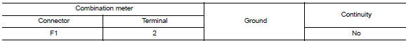
Is the inspection result normal?
YES >> Replace the combination meter. Refer to MWI"Removal and Installation" (Type B) or MWI "Removal and Installation" (Type A).
NO >> Repair or replace the harness or connectors.
 L Terminal circuit (open)
Description The "L" terminal circuit controls the charge warning lamp. The charge warning lamp turns ON when the ignition switch is set to ON or START. When the generator is providing sufficient ...
S Terminal circuit
Description The output voltage of the generator is controlled by the IC regulator at terminal "S" detecting the input voltage from battery. The "S" terminal circuit detects the battery voltage ...
Other materials:
Service data and specifications
(SDS)
General Specifications
Engine type
HR16DE
Type of clutch control
Hydraulic
Clutch disc
Facing size (Outer dia. × Inner dia. × Thickness)
200 × 140 × 3.1 (7.87 × 5.51 × 0.122)
Recommended clutch fluid
Refer to M ...
Oil
Description
MAINTENANCE OF OIL LEVEL
The compressor oil is circulating in the system together with the
refrigerant. It is necessary to fill compressor
with oil when replacing A/C system parts or when a large amount of refrigerant
leakage is detected. It is important
to always maintain oil l ...
Categories
- Manuals Home
- Nissan Versa Owners Manual
- Nissan Versa Service Manual
- Video Guides
- Questions & Answers
- External Resources
- Latest Updates
- Most Popular
- Sitemap
- Search the site
- Privacy Policy
- Contact Us

0.0047