Nissan Versa (N17): S Terminal circuit
Description
The output voltage of the generator is controlled by the IC regulator at terminal "S" detecting the input voltage from battery.
The "S" terminal circuit detects the battery voltage to adjust the generator output voltage with the IC voltage regulator.
Diagnosis Procedure
Regarding Wiring Diagram information. Refer to CHG "Wiring Diagram".
1.CHECK "S" TERMINAL CONNECTION
1. Turn ignition switch OFF.
2. Check if "S" terminal is clean and tight.
Is the inspection result normal?
YES >> GO TO 2.
NO >> Repair "S" terminal connection. Confirm repair by performing complete Charging system test using EXP-800 NI or GR8-1200 NI (if available). Refer to the applicable Instruction Manual for proper testing procedures.
2.CHECK "S" TERMINAL CIRCUIT
Check voltage between generator harness connector and ground.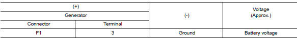
Is the inspection result normal?
YES >> Refer to CHG "Work Flow (With EXP-800 NI or GR8-1200 NI)" or CHG "Work Flow (Without EXP-800 NI or GR8-1200 NI)".
NO >> Check harness for open between generator and fuse.
SYMPTOM DIAGNOSIS
CHARGING SYSTEM
Symptom Table
|
Symptom |
Reference |
| Battery discharged | Refer to CHG "Work Flow (With EXP-800 NI or GR8-1200 NI)" or CHG "Work Flow (Without EXP-800 NI or GR8-1200 NI)". |
| The charge warning lamp does not illuminate when the ignition switch is set to ON. | |
| The charge warning lamp does not turn OFF after the engine starts. | |
| The charging warning lamp turns ON when increasing the engine speed. |
REMOVAL AND INSTALLATION
 L Terminal circuit (short)
Description The terminal "L" circuit controls the charge warning lamp. The charge warning lamp turns ON when the ignition switch is set to ON or START. When the generator is providing sufficient v ...
Generator
Exploded View 1. Generator bracket bolt 2. Generator bracket 3. Generator bolt 4. Generator 5. "B" terminal harness 6. "B" terminal nut 7. Generator harness connector Removal and Installatio ...
Other materials:
Readiness for inspection/maintenance (I/M) test
Due to legal requirements in some states and
Canadian Provinces, your vehicle may be required
to be in what is called the "ready condition"
for an Inspection/Maintenance (I/M) test of
the emission control system.
The vehicle is set to the "ready condition" when it
is driven through certain d ...
P0607 ECM
DTC Logic
DTC DETECTION LOGIC
DTC No.
Trouble diagnosis
(Trouble diagnosis content)
DTC detecting condition
Possible cause
P0607
ECM
(CAN communication bus)
When detecting error during the initial diagnosis
of CAN controller of ECM.
ECM
DTC CO ...
Categories
- Manuals Home
- Nissan Versa Owners Manual
- Nissan Versa Service Manual
- Video Guides
- Questions & Answers
- External Resources
- Latest Updates
- Most Popular
- Sitemap
- Search the site
- Privacy Policy
- Contact Us

0.0063