Nissan Versa (N17): Microphone
Removal and Installation
REMOVAL
1. Remove the microphone (1) from the headlining using a suitable tool.
 Clip
Clip
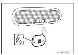
2. Disconnect the harness connector from microphone and remove.
INSTALLATION
Installation is in the reverse order of removal.
ANTENNA FEEDER
Feeder Layout
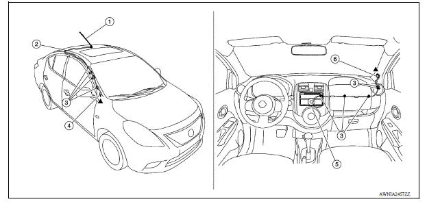
1. Antenna mast 2. Antenna feed 3. Clip 4. Harness connector 5. Audio unit 6. Harness connector
 Bluetooth antenna
Removal and Installation REMOVAL 1. Remove the rear seat cushion assembly. Refer to SE "Removal and Installation - Seat Cushion Assembly". 2. Remove the rear step plate (RH). 3. Remov ...
Roof antenna
Exploded View 1. Antenna mast 2. Antenna base Removal and Installation REMOVAL 1. Remove the headlining. Refer to INT "Removal and Installation". 2. Disconnect the antenna cable. ...
Other materials:
Precautions
Precaution for Supplemental Restraint System
(SRS) "AIR BAG" and "SEAT BELT PRE-TENSIONER"
The Supplemental Restraint System such as "AIR BAG" and "SEAT BELT PRE-TENSIONER",
used along
with a front seat belt, helps to reduce the risk or severity of injury to the
driver and ...
Trunk lid lock
TRUNK LID LOCK : Removal and Installation
REMOVAL
1. Remove trunk lid finisher (if equipped). Refer to INT "Removal and
Installation".
2. Release rod holder (1) by lifting upward, and then separate trunk
lid lock rod (3) from trunk lid lock assembly (2).
3. Remove trunk lid lock ...
Categories
- Manuals Home
- Nissan Versa Owners Manual
- Nissan Versa Service Manual
- Video Guides
- Questions & Answers
- External Resources
- Latest Updates
- Most Popular
- Sitemap
- Search the site
- Privacy Policy
- Contact Us

0.0047