Nissan Versa (N17): NATS antenna AMP
Removal and Installation
REMOVAL
1. Remove the instrument lower panel LH. Refer to IP"Removal and Installation".
2. Release the NATS antenna amp. pawls and remove NATS antenna amp. (1).
 : Pawl
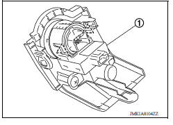
INSTALLATION
Installation is in the reverse order of removal.
 Security indicator lamp does not
turn on or blink
Security indicator lamp does not
turn on or blinkPush-button ignition switch
Removal and Installation REMOVAL 1. Remove NATS antenna amp. Refer to SEC "Removal and Installation". 2. Release the push-button ignition switch pawls and remove the push-button ignition ...
Other materials:
Maintenance under severe operating conditions
The maintenance intervals shown on the preceding pages are for normal
operating conditions. If the vehicle is mainly operated under severe driving
conditions as shown below, more frequent maintenance must be performed on the
following items as shown in the table.
Severe driving conditions
...
Front fog lamp system
FRONT FOG LAMP SYSTEM : System Diagram
FRONT FOG LAMP SYSTEM : System Description
FRONT FOG LAMP OPERATION
When the combination switch (lighting and turn signal switch) is in front fog
lamp ON position and also in 1ST
or 2ND position (headlamp is ON), the BCM detects FR FOG ON and the HEAD ...
Categories
- Manuals Home
- Nissan Versa Owners Manual
- Nissan Versa Service Manual
- Video Guides
- Questions & Answers
- External Resources
- Latest Updates
- Most Popular
- Sitemap
- Search the site
- Privacy Policy
- Contact Us

0.0244