Nissan Versa (N17): P0117, P0118 ECT sensor
DTC Logic
DTC DETECTION LOGIC
| DTC No. | Trouble diagnosis name (Trouble diagnosis content) | DTC detecting condition | Possible cause |
| P0117 | Engine coolant temperature sensor circuit low input | An excessively low voltage from the sensor is sent to ECM |
|
| P0118 | Engine coolant temperature sensor circuit high input | An excessively low voltage from the sensor is sent to ECM |
DTC CONFIRMATION PROCEDURE
1.PRECONDITIONING
If DTC Confirmation Procedure has been previously conducted, always perform the following procedure before conducting the next test.
- Turn ignition switch OFF and wait at least 10 seconds.
- Turn ignition switch ON.
- Turn ignition switch OFF and wait at least 10 seconds.
>> GO TO 2.
2.PERFORM DTC CONFIRMATION PROCEDURE
- Turn ignition switch ON and wait at least 5 seconds.
- Check DTC.
Is DTC detected?
YES >> Go to EC, "Diagnosis Procedure".
NO >> INSPECTION END
Diagnosis Procedure
1.CHECK GROUND CONNECTION
- Turn ignition switch OFF.
- Check ground connection E. Refer to Ground Inspection in GI, "Circuit Inspection".
Is the inspection result normal?
YES >> GO TO 2.
NO >> Repair or replace ground connection.
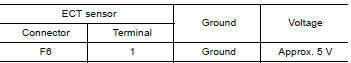
2.CHECK ECT SENSOR POWER SUPPLY CIRCUIT
- Disconnect engine coolant temperature (ECT) sensor harness connector.
- Turn ignition switch ON.
- Check the voltage between ECT sensor harness connector and ground.
Is the inspection result normal?
YES >> GO TO 3.
NO >> Repair open circuit or short to ground or short to power in harness or connectors.
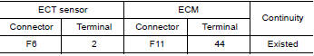
3.CHECK ECT SENSOR GROUND CIRCUIT FOR OPEN AND SHORT
- Turn ignition switch OFF.
- Disconnect ECM harness connector.
- Check the continuity between ECT sensor harness connector and ECM harness connector.
4. Also check harness for short to ground and short to power.
Is the inspection result normal?
YES >> GO TO 4.
NO >> Repair open circuit or short to ground or short to power in harness or connectors.
4.CHECK ENGINE COOLANT TEMPERATURE SENSOR
Refer to GI, "Circuit Inspection".
Is the inspection result normal?
YES >> GO TO 5.
NO >> Replace engine coolant temperature sensor. Refer to CO, "Exploded View".
5.CHECK INTERMITTENT INCIDENT
Refer to GI, "Intermittent Incident".
>> INSPECTION END
Component Inspection
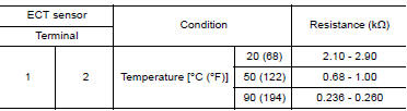
1.CHECK ENGINE COOLANT TEMPERATURE (ECT) SENSOR
- Turn ignition switch OFF.
- Disconnect ECT sensor harness connector.
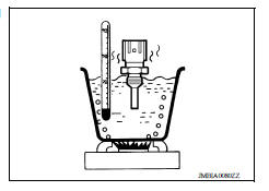
- Remove ECT sensor.
- Check resistance between ECT sensor terminals by heating with hot water as shown in the figure.
Is the inspection result normal?
YES >> INSPECTION END
NO >> Replace engine coolant temperature sensor. Refer to CO, "Exploded View".
 P0116 ECT sensor
Other materials:
VDC/TCS/ABS
Symptom Table
If ABS warning lamp and SLIP indicator lamp turn ON, perform self-diagnosis.
NOTE:
The ABS does not operate when the speed is 10 km/h (6 MPH) or less.
Under the following conditions, ABS is activated and vibration is
felt when brake pedal is lightly depressed (just place ...
Rear power window switch
Removal and Installation
REMOVAL
1. Remove rear power window switch finisher (1) assembly using a
suitable tool (A).
Pawl
2. Disconnect the harness connector from the rear power window switch.
3. Separate rear power window switch (1) from rear power window
switch finisher using a suitable ...
Categories
- Manuals Home
- Nissan Versa Owners Manual
- Nissan Versa Service Manual
- Video Guides
- Questions & Answers
- External Resources
- Latest Updates
- Most Popular
- Sitemap
- Search the site
- Privacy Policy
- Contact Us

0.0116