Nissan Versa (N17): Power supply and ground circuit
With intelligent key
WITH INTELLIGENT KEY : Diagnosis Procedure
Regarding Wiring Diagram information, refer to BCS "Wiring Diagram".
1.CHECK FUSES AND FUSIBLE LINK
Check that the following fuses and fusible link are not blown.
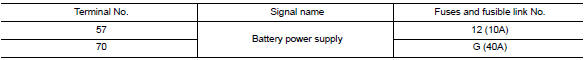
Is the fuse blown?
YES >> Replace the blown fuse or fusible link after repairing the affected circuit.
NO >> GO TO 2.
2.CHECK POWER SUPPLY CIRCUIT
- Disconnect BCM connector M99.
- Check voltage between BCM connector M99 and ground.
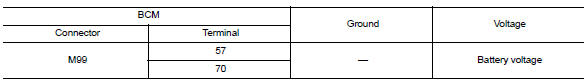
Is the inspection result normal?
YES >> GO TO 3.
NO >> Repair harness or connector.
3.CHECK GROUND CIRCUIT
Check continuity between BCM connector M99 and ground.
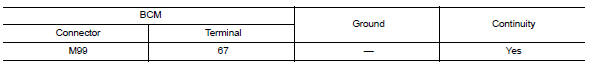
Is the inspection result normal?
YES >> Inspection End.
NO >> Repair harness or connector
Without intelligent key
WITHOUT INTELLIGENT KEY : Diagnosis Procedure
Regarding Wiring Diagram information, refer to BCS "Wiring Diagram".
1.CHECK FUSES AND FUSIBLE LINK
Check that the following fuses and fusible link are not blown.
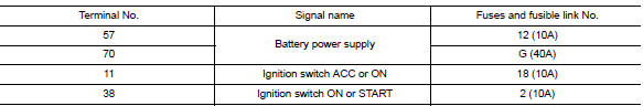
Is the fuse blown?
YES >> Replace the blown fuse or fusible link after repairing the affected circuit.
NO >> GO TO 2.
2.CHECK POWER SUPPLY CIRCUIT
- Turn ignition switch OFF.
- Disconnect BCM connectors.
- Check voltage between BCM connector and ground.
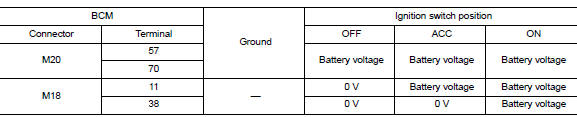
Is the inspection result normal?
YES >> GO TO 3.
NO >> Repair harness or connector.
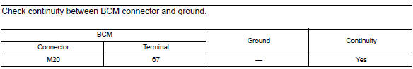
3.CHECK GROUND CIRCUIT
Check continuity between BCM connector and ground.
Is the inspection result normal?
YES >> Inspection End.
NO >> Repair harness or connector.
SYMPTOM DIAGNOSIS
TPMS SYMPTOMS
Symptom Table
| Symptom | Reference |
| Low tire pressure warning lamp does not turn ON. |
WT |
| Low tire pressure warning lamp does not turn OFF. | |
| Low tire pressure warning lamp blinks. | |
| ID registration cannot be completed |
 Low tire pressure warning lamp
Component Function Check 1.CHECK THE ILLUMINATION OF THE LOW TIRE PRESSURE WARNING LAMP Check that the low tire pressure warning lamp is turned OFF after illuminating for approximately 1 second, ...
Low tire pressure warning lamp
does not turn on
Diagnosis Procedure NOTE: The Signal Tech II Tool (J-50190) can be used to perform the following functions. Refer to the Signal Tech II User Guide for additional information. Activate and dis ...
Other materials:
IDLE SPEED
Inspection
1.CHECK IDLE SPEED
With CONSULT
Check idle speed in "DATA MONITOR" mode with CONSULT.
Without CONSULT
Check idle speed by installing the pulse type tachometer clamp on the loop
wire or on suitable high-tension
wire which installed between No.1 ignition coil and No.1 spark plug.
...
Control cable
Exploded View
1. Bracket B 2. Lock plate 3. Transaxle assembly
4. Bracket A 5. Control cable 6. CVT shift selector assembly
A: Manual lever B: Grommet
Removal and Installation
CAUTION:
Always apply the parking brake before performing removal and installation.
REMOVAL
Remove the batt ...
Categories
- Manuals Home
- Nissan Versa Owners Manual
- Nissan Versa Service Manual
- Video Guides
- Questions & Answers
- External Resources
- Latest Updates
- Most Popular
- Sitemap
- Search the site
- Privacy Policy
- Contact Us

0.0056