
Nissan Versa (N17): Power supply routing circuit
Wiring Diagram - Battery Power Supply -
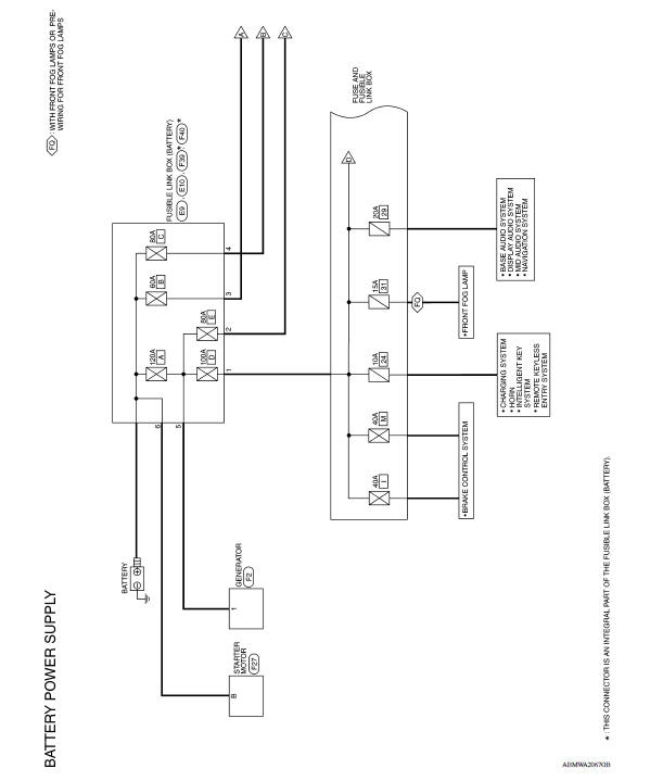
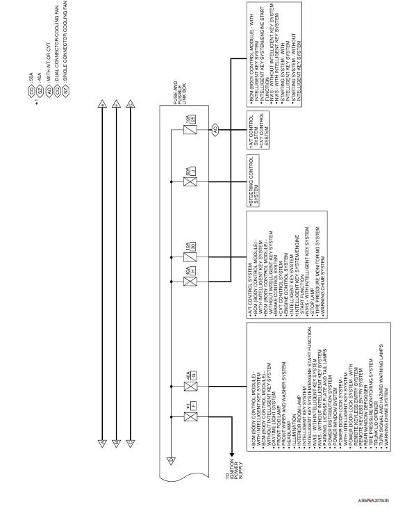
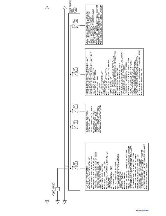
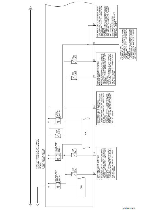
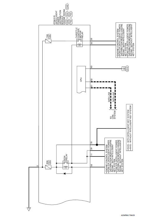
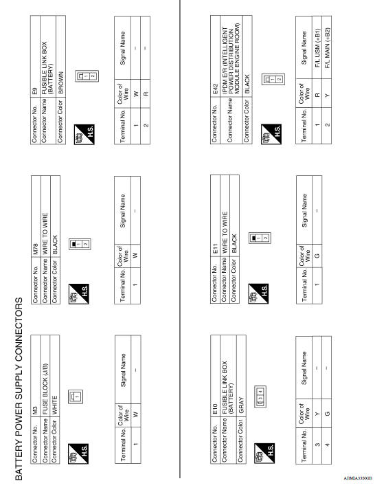
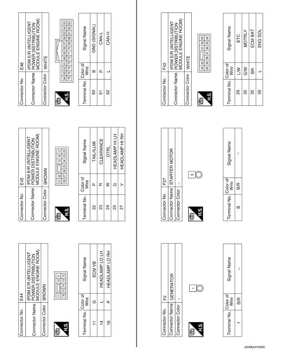
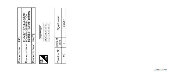
Wiring Diagram - Accessory Power Supply -
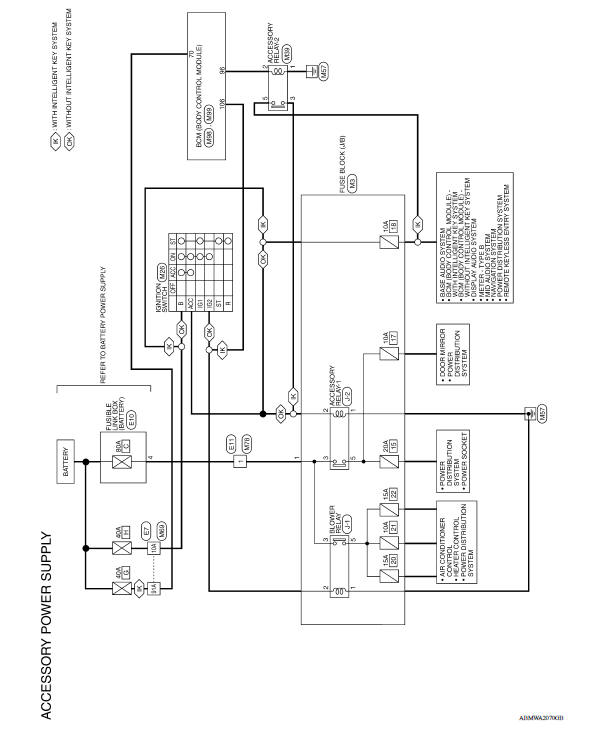
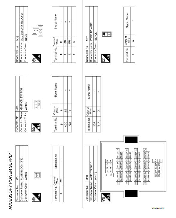
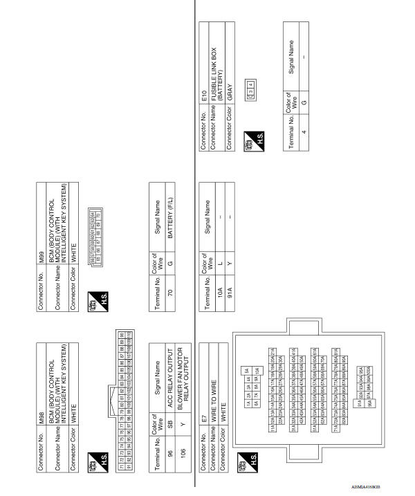
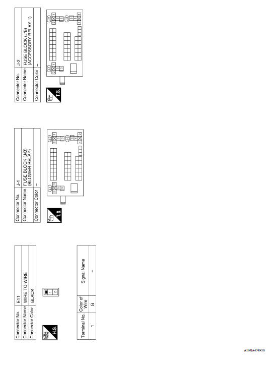
Wiring Diagram - Ignition Power Supply -
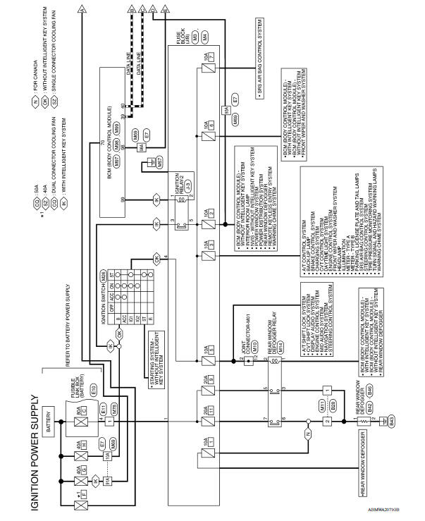
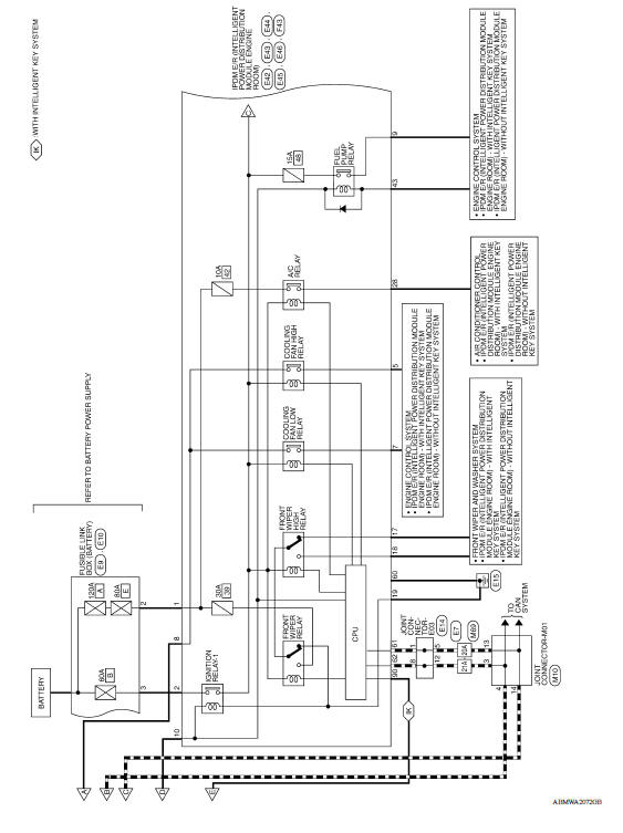
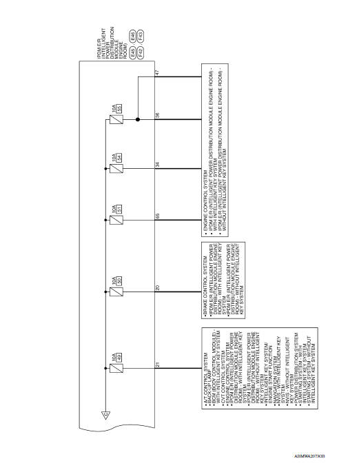
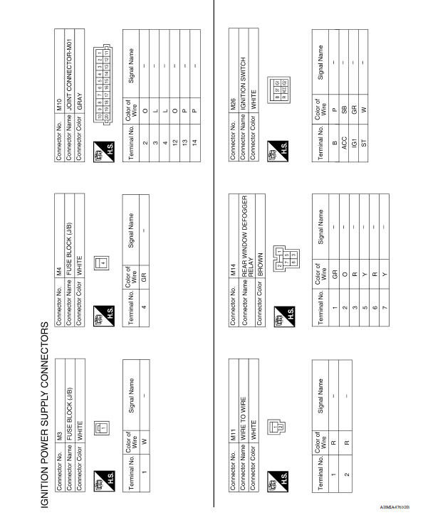
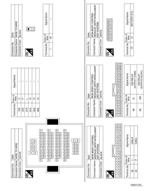
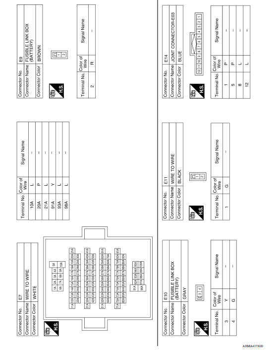
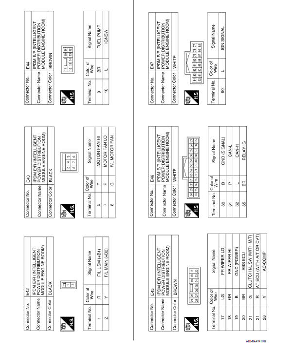
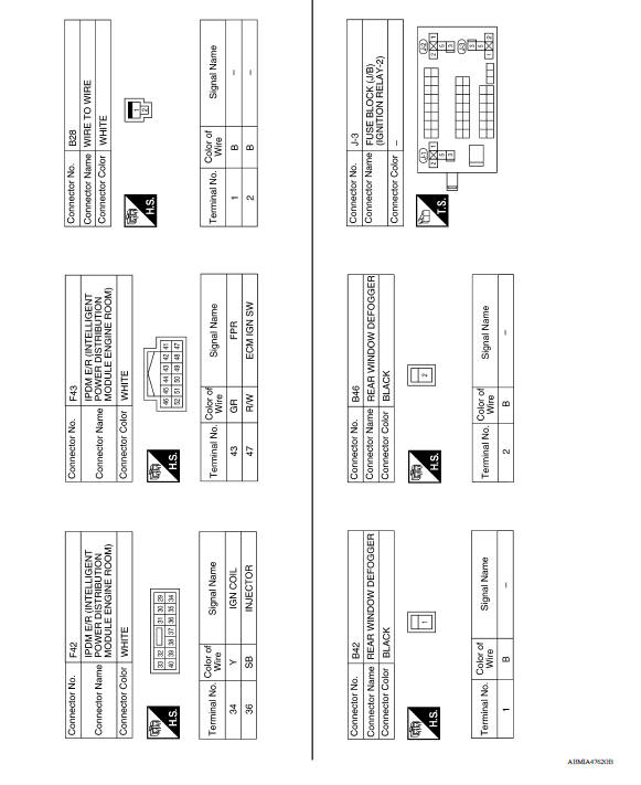
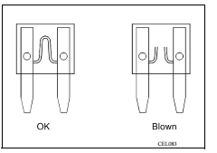
Fuse
- If fuse is blown, be sure to eliminate cause of malfunction before installing new fuse.
- Use fuse of specified rating. Never use fuse of more than specified rating.
- Do not partially install fuse; always insert it into fuse holder properly.
- Remove fuse for "ELECTRICAL PARTS (BAT)" if vehicle is not used for a long period of time.
Fusible Link
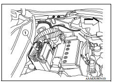
A melted fusible link can be detected either by visual inspection or by feeling with finger tip. If its condition is questionable, use circuit tester or test lamp.
1 : Fusible link
 Vehicle front
CAUTION:
- If fusible link should melt, it is possible that critical circuit (power supply or large current carrying circuit) is shorted. In such a case, carefully check and eliminate cause of malfunction.
- Never wrap outside of fusible link with vinyl tape. Important: Never let fusible link touch any other wiring harness, vinyl or rubber parts.
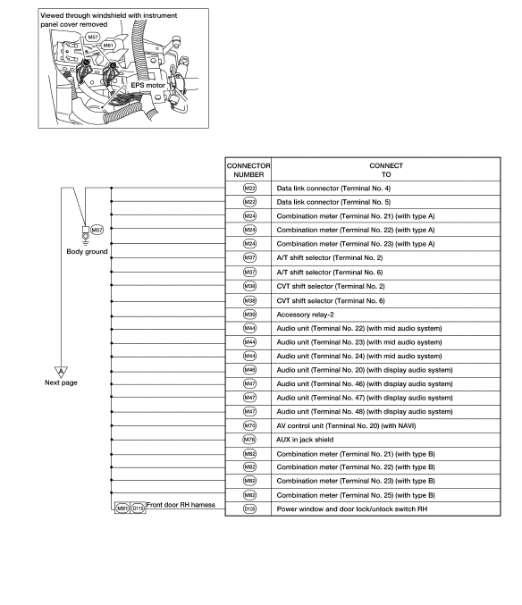
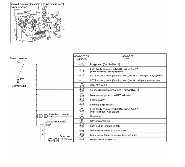
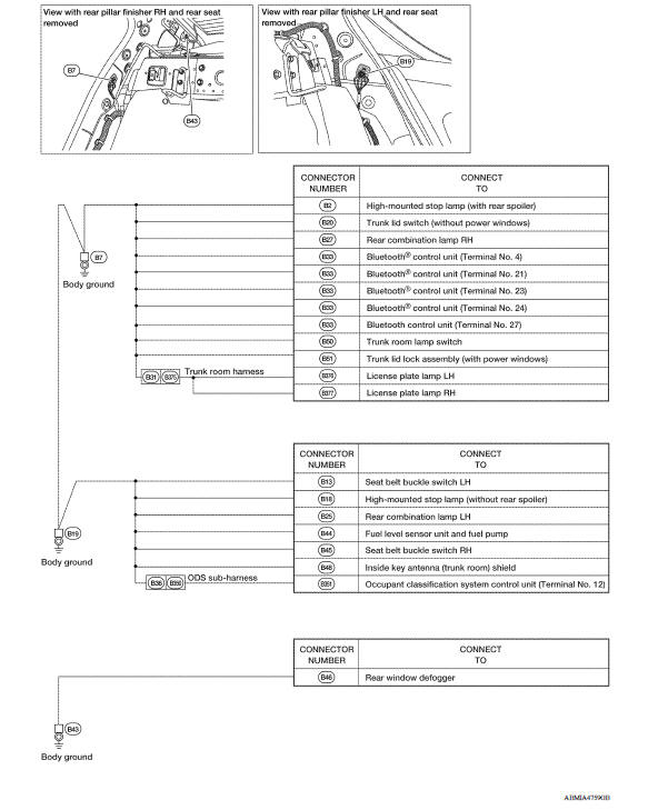
GROUND
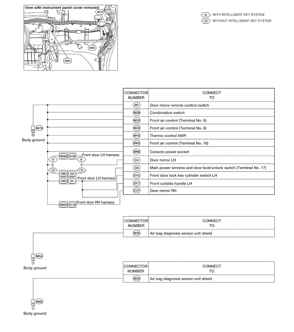
Ground Distribution
MAIN HARNESS
ENGINE ROOM HARNESS
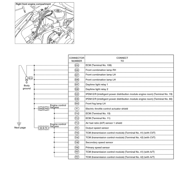
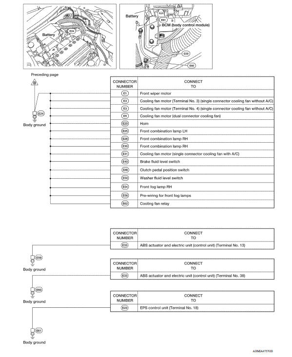
ENGINE CONTROL HARNESS
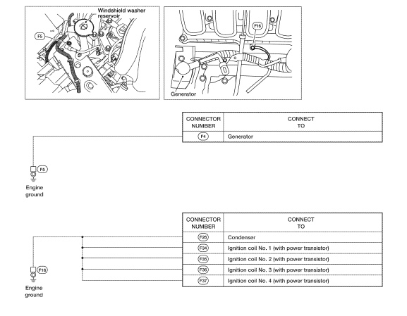
BODY HARNESS
 Battery
Harness
Harness Layout HOW TO READ HARNESS LAYOUT The following Harness Layouts use a map style grid to help locate connectors on the drawings: Main Harness Engine Room Harness Engine Room Harnes ...
Other materials:
Rear drum brake
Exploded View
1. Shoe hold pin 2. Back plate 3. Plug
4. Brake shoe 5. Spring 6. Upper spring
7. Adjuster 8. Return spring 9. Brake drum
10. Boot 11. Piston 12. Piston cup
13. Spring 14. Wheel cylinder 15. Bleeder valve
16. Cap
1: Apply rubber grease.
2: Apply PBC (Poly Butyl Cuprysil) ...
Diagnosis and repair work flow
Work Flow
OVERALL SEQUENCE
*1 SRC "Diagnosis Description" *2 SRC "SRS Operation Check" *3 SRC
"Trouble Diagnosis with
CONSULT" *4 SRC "Trouble Diagnosis without CONSULT"
DETAILED WORK FLOW
1.CUSTOMER INFORMATION
Get detailed information from the c ...
Categories
- Manuals Home
- Nissan Versa Owners Manual
- Nissan Versa Service Manual
- Video Guides
- Questions & Answers
- External Resources
- Latest Updates
- Most Popular
- Sitemap
- Search the site
- Privacy Policy
- Contact Us

0.0058