Nissan Versa (N17): Precautions
Precaution for Supplemental Restraint System (SRS) "AIR BAG" and "SEAT BELT PRE-TENSIONER"
The Supplemental Restraint System such as "AIR BAG" and "SEAT BELT PRE-TENSIONER", used along with a front seat belt, helps to reduce the risk or severity of injury to the driver and front passenger for certain types of collision. This system includes seat belt switch inputs and dual stage front air bag modules. The SRS system uses the seat belt switches to determine the front air bag deployment, and may only deploy one front air bag, depending on the severity of a collision and whether the front occupants are belted or unbelted.
Information necessary to service the system safely is included in the SR and SB section of this Service Manual.
WARNING:
- To avoid rendering the SRS inoperative, which could increase the risk of personal injury or death in the event of a collision which would result in air bag inflation, all maintenance must be performed by an authorized NISSAN/INFINITI dealer.
- Improper maintenance, including incorrect removal and installation of the SRS, can lead to personal injury caused by unintentional activation of the system. For removal of Spiral Cable and Air Bag Module, see the SR section.
- Do not use electrical test equipment on any circuit related to the SRS unless instructed to in this Service Manual. SRS wiring harnesses can be identified by yellow and/or orange harnesses or harness connectors.
PRECAUTIONS WHEN USING POWER TOOLS (AIR OR ELECTRIC) AND HAMMERS
WARNING:
- When working near the Airbag Diagnosis Sensor Unit or other Airbag System sensors with the Ignition ON or engine running, DO NOT use air or electric power tools or strike near the sensor(s) with a hammer. Heavy vibration could activate the sensor(s) and deploy the air bag(s), possibly causing serious injury.
- When using air or electric power tools or hammers, always switch the Ignition OFF, disconnect the battery, and wait at least 3 minutes before performing any service.
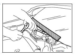
Precaution for Procedure without Cowl Top Cover
When performing the procedure after removing cowl top cover, cover the lower end of windshield with urethane, etc to prevent damage to windshield.
Precaution for Brake System
CAUTION:
- Refer to MA "Fluids and Lubricants" for recommended brake fluid.
- Do not reuse drained brake fluid.
- Be careful not to splash brake fluid on painted areas; it may cause paint damage. If brake fluid is splashed on painted areas, wash it away with water immediately.
- To clean or wash all parts of master cylinder and disc brake caliper, use clean brake fluid.
- Do not use mineral oils such as gasoline or kerosene. They will ruin rubber parts of the hydraulic system.
- Use flare nut wrench when removing and installing brake tube.
- If a brake fluid leak is found, the part must be disassembled without fail. Then it has to be replaced with a new one if a defect exists.
- Turn the ignition switch OFF and remove the connector of the ABS actuator and electric unit (control unit) or the battery terminal before performing the work.
- Always torque brake lines when installing.
Precaution for Brake Control
- During ABS operation, the brake pedal may vibrate lightly and a mechanical noise may be heard. This is normal.
- Just after starting vehicle, the brake pedal may vibrate or a motor operating noise may be heard from engine compartment. This is a normal status of operation check.
- Stopping distance may be longer than that of vehicles without ABS when vehicle drives on rough, gravel, or snow-covered (fresh, deep snow) roads.
- When an error is indicated by ABS or another warning lamp, collect all
necessary information from customer
(what symptoms are present under what conditions) and check for simple
causes before starting diagnosis.
Besides electrical system inspection, check booster operation, brake fluid level, and fluid leaks.
- If incorrect tire sizes or types are installed on the vehicle or brake pads are not Genuine NISSAN parts, stopping distance or steering stability may deteriorate.
- If there is a radio, antenna or related wiring near control module, ABS function may have a malfunction or error.
- If aftermarket parts (car stereo, CD player, etc.) have been installed, check for incidents such as harness pinches, open circuits or improper wiring.
- If the following components are replaced with non-genuine components or modified, the VDC OFF indicator lamp and SLIP indicator lamp may turn on or the VDC system may not operate properly. Components related to suspension (shock absorbers, struts, springs, bushings, etc.), tires, wheels (exclude specified size), components related to brake system (pads, rotors, calipers, etc.), components related to engine (muffler, ECM, etc.), components related to body reinforcement (roll bar, tower bar, etc.).
- Driving with broken or excessively worn suspension components, tires or brake system components may cause the VDC OFF indicator lamp and the SLIP indicator lamp to turn on, and the VDC system may not operate properly.
- When the TCS or VDC is activated by sudden acceleration or sudden turn, some noise may occur. The noise is a result of the normal operation of the TCS and VDC.
- When driving on roads which have extreme slopes (such as mountainous roads) or high banks (such as sharp curves on a freeway), the VDC may not operate normally, or the VDC warning lamp and the SLIP indicator lamp may turn on. This is not a problem if normal operation can be resumed after restarting the engine.
- Sudden turns (such as spin turns, acceleration turns), drifting, etc. with VDC turned off may cause the yaw rate/side/decel G sensor to indicate a problem. This is not a problem if normal operation can be resumed after restarting the engine.
Precaution for CAN System
- Do not apply voltage of 7.0V or higher to terminal to be measured.
- Maximum open terminal voltage of tester in use must be less than 7.0V.
- Before checking harnesses, turn ignition switch OFF and disconnect battery negative cable.
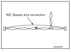
- Area to be repaired must be soldered and wrapped with tape.
Make sure that fraying of twisted wire is within 110 mm (4.33 in).
- Do not make a bypass connection to repaired area. (If the circuit is bypassed, characteristics of twisted wire will be lost.)
PREPARATION
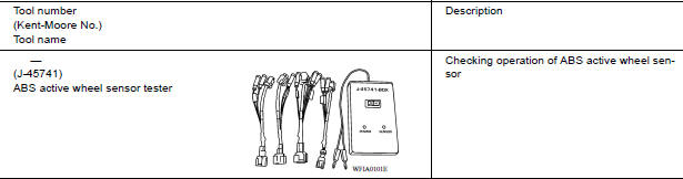
Special Service Tool
The actual shapes of Kent-Moore tools may differ from those of special service tools illustrated here.
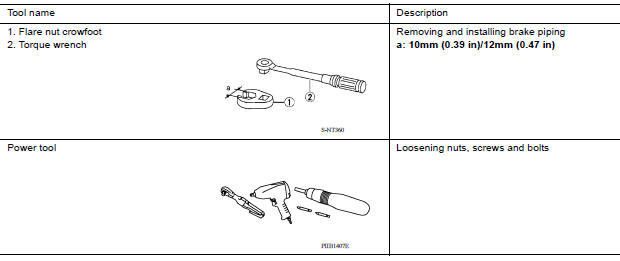
Commercial Service Tool
SYSTEM DESCRIPTION
 Parking brake control
Exploded View 1. Parking brake lever assembly 2. Adjusting nut 3. Parking brake switch 4. Front cable 5. Rear cable (LH) 6. Rear cable (RH) Removal and Installation REMOVAL Remove rear wh ...
Component parts
Component Parts Location 1 ABS actuator and electric unit (control unit) 2 IPDM E/R 3 Brake fluid level switch (view with IPDM E/R removed) 4 Front wheel sensor 5 Rear wheel sensor 6 VDC OFF ...
Other materials:
Engine control system
ENGINE CONTROL SYSTEM : System Diagram
NOTE:
Battery current sensor is used in CVT models.
ENGINE CONTROL SYSTEM : System Description
ECM performs various controls such as fuel injection control and ignition
timing control.
ENGINE CONTROL SYSTEM : Fail Safe
NON DTC RELATED ITEM
...
P0965 Pressure control solenoid B
DTC Logic
DTC DETECTION LOGIC
DTC
Trouble diagnosis name
DTC detection condition
Possible causes
P0965
Pressure control solenoid B
control circuit range performance
The detection conditions continuously for 5
seconds or more under the following diagnosis
con ...
Categories
- Manuals Home
- Nissan Versa Owners Manual
- Nissan Versa Service Manual
- Video Guides
- Questions & Answers
- External Resources
- Latest Updates
- Most Popular
- Sitemap
- Search the site
- Privacy Policy
- Contact Us

0.0091