Nissan Versa (N17): Precautions
Precaution for Supplemental Restraint System (SRS) "AIR BAG" and "SEAT BELT PRE-TENSIONER"
The Supplemental Restraint System such as "AIR BAG" and "SEAT BELT PRE-TENSIONER", used along with a front seat belt, helps to reduce the risk or severity of injury to the driver and front passenger for certain types of collision. This system includes seat belt switch inputs and dual stage front air bag modules. The SRS system uses the seat belt switches to determine the front air bag deployment, and may only deploy one front air bag, depending on the severity of a collision and whether the front occupants are belted or unbelted.
Information necessary to service the system safely is included in the SR and SB section of this Service Manual.
WARNING:
- To avoid rendering the SRS inoperative, which could increase the risk of personal injury or death in the event of a collision which would result in air bag inflation, all maintenance must be performed by an authorized NISSAN/INFINITI dealer.
- Improper maintenance, including incorrect removal and installation of the SRS, can lead to personal injury caused by unintentional activation of the system. For removal of Spiral Cable and Air Bag Module, see the SR section.
- Do not use electrical test equipment on any circuit related to the SRS unless instructed to in this Service Manual. SRS wiring harnesses can be identified by yellow and/or orange harnesses or harness connectors.
PRECAUTIONS WHEN USING POWER TOOLS (AIR OR ELECTRIC) AND HAMMERS
WARNING:
- When working near the Airbag Diagnosis Sensor Unit or other Airbag System sensors with the Ignition ON or engine running, DO NOT use air or electric power tools or strike near the sensor(s) with a hammer. Heavy vibration could activate the sensor(s) and deploy the air bag(s), possibly causing serious injury.
- When using air or electric power tools or hammers, always switch the Ignition OFF, disconnect the battery, and wait at least 3 minutes before performing any service.
Precaution for Work
- When removing or disassembling each component, be careful not to damage or deform it. If a component may be subject to interference, be sure to protect it with a shop cloth.
- When removing (disengaging) components with a screwdriver or similar tool, be sure to wrap the component with a shop cloth or vinyl tape to protect it.
- Protect the removed parts with a shop cloth and prevent them from being dropped.
- Replace a deformed or damaged clip.
- If a part is specified as a non-reusable part, always replace it with a new one.
- Be sure to tighten bolts and nuts securely to the specified torque.
- After installation is complete, be sure to check that each part works properly.
- Follow the steps below to clean components:
- Water soluble dirt:
- Dip a soft cloth into lukewarm water, wring the water out of the cloth and wipe the dirty area.
- Then rub with a soft, dry cloth.
- Oily dirt:
- Dip a soft cloth into lukewarm water with mild detergent (concentration: within 2 to 3%) and wipe the dirty area.
- Then dip a cloth into fresh water, wring the water out of the cloth and wipe the detergent off.
- Then rub with a soft, dry cloth.
- Do not use organic solvent such as thinner, benzene, alcohol or gasoline.
- For genuine leather seats, use a genuine leather seat cleaner.
PREPARATION
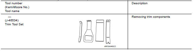
Special Service Tool
The actual shapes of Kent-Moore tools may differ from those of special service tools illustrated here.
SYSTEM DESCRIPTION
COMPONENT PARTS
Component Parts Location
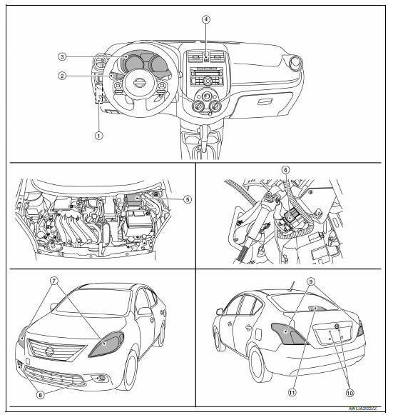
1. BCM 2. Combination switch (lighting and turn signal switch) 3. Combination meter 4. Hazard switch 5. IPDM E/R, Daytime light relays 1 and 2 (if equipped), Front fog lamp relay (if equipped) 6. Stop lamp switch 7. Front combination lamp LH, RH 8. Front fog lamp LH, RH (if equipped) 9. Rear combination lamp LH, RH 10. License plate lamp LH, RH 11. High mounted stop lamp
Component Description
| Part name | Description |
| BCM | Controls the exterior lighting system. |
| Combination meter | - Blinks the turn signal indicator lamp and outputs the turn signal
operating sound with integrated buzzer according to the request
from BCM (via CAN communication). - Turns the tail lamp indicator lamp and high beam indicator lamp ON according to the request from BCM (via CAN communication). |
| Combination switch (lighting and turn signal switch) | Refer to BCS "COMBINATION SWITCH READING SYSTEM : System Description" (with Intelligent Key) or BCS "COMBINATION SWITCH READING SYSTEM : System Description" (without Intelligent Key). |
| Hazard switch | Hazard flasher request signal is output to the BCM. |
| IPDM E/R | Controls the integrated relay, and supplies voltage to the load according to the request from BCM (via CAN communication). |
| Stop lamp switch | Stop lamp signal is output to the rear combination lamps and highmounted stop lamp. |
SYSTEM
 Door mirror remote control
switch
Door mirror remote control
switch
Removal and Installation REMOVAL 1. Remove the instrument lower panel LH (1). Refer to IP "Removal and Installation". 2. Remove door mirror remote control switch (1) from the instrum ...
Headlamp system
HEADLAMP SYSTEM : System Diagram HEADLAMP SYSTEM : System Description LOW BEAM OPERATION When the lighting switch is in 2nd position, the BCM receives input requesting the headlamps to illu ...
Other materials:
Vehicle Dynamic Control (VDC) off switch
The vehicle should be driven with the VDC system
on for most driving conditions.
If the vehicle is stuck in mud or snow, the VDC
system reduces the engine output to reduce
wheel spin. The engine speed will be reduced
even if the accelerator is depressed to the floor. If
maximum engine po ...
Readiness for inspection/maintenance (I/M) test
Due to legal requirements in some states and
Canadian Provinces, your vehicle may be required
to be in what is called the "ready condition"
for an Inspection/Maintenance (I/M) test of
the emission control system.
The vehicle is set to the "ready condition" when it
is driven through certain d ...
Categories
- Manuals Home
- Nissan Versa Owners Manual
- Nissan Versa Service Manual
- Video Guides
- Questions & Answers
- External Resources
- Latest Updates
- Most Popular
- Sitemap
- Search the site
- Privacy Policy
- Contact Us

0.0064