Nissan Versa (N17): Precautions
Precaution for Supplemental Restraint System (SRS) "AIR BAG" and "SEAT BELT PRE-TENSIONER"
The Supplemental Restraint System such as "AIR BAG" and "SEAT BELT PRE-TENSIONER", used along with a front seat belt, helps to reduce the risk or severity of injury to the driver and front passenger for certain types of collision. This system includes seat belt switch inputs and dual stage front air bag modules. The SRS system uses the seat belt switches to determine the front air bag deployment, and may only deploy one front air bag, depending on the severity of a collision and whether the front occupants are belted or unbelted.
Information necessary to service the system safely is included in the SR and SB section of this Service Manual.
WARNING:
- To avoid rendering the SRS inoperative, which could increase the risk of personal injury or death in the event of a collision which would result in air bag inflation, all maintenance must be performed by an authorized NISSAN/INFINITI dealer.
- Improper maintenance, including incorrect removal and installation of the SRS, can lead to personal injury caused by unintentional activation of the system. For removal of Spiral Cable and Air Bag Module, see the SR section.
- Do not use electrical test equipment on any circuit related to the SRS unless instructed to in this Service Manual. SRS wiring harnesses can be identified by yellow and/or orange harnesses or harness connectors.
PRECAUTIONS WHEN USING POWER TOOLS (AIR OR ELECTRIC) AND HAMMERS
WARNING:
- When working near the Airbag Diagnosis Sensor Unit or other Airbag System sensors with the Ignition ON or engine running, DO NOT use air or electric power tools or strike near the sensor(s) with a hammer. Heavy vibration could activate the sensor(s) and deploy the air bag(s), possibly causing serious injury.
- When using air or electric power tools or hammers, always switch the Ignition OFF, disconnect the battery, and wait at least 3 minutes before performing any service.
PREPARATION
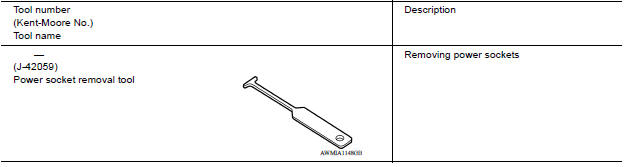
Special Service Tool
The actual shapes of Kent-Moore tools may differ from those of special service tools illustrated here.
WIRING DIAGRAM
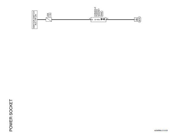
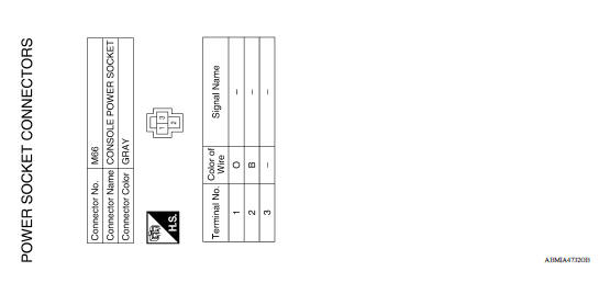
POWER SOCKET
Wiring Diagram
REMOVAL AND INSTALLATION
 Power supply, ground & circuit elements (PG)
Power socket
Exploded View 1. Cap 2. Inner socket 3. Ring Removal and Installation CONSOLE POWER SOCKET Removal 1. Remove the fuse for the power socket. 2. Insert one end of the Tool (A) into one of the ...
Other materials:
Windows
Power windows (if so equipped)
WARNING
Make sure that all passengers have
their hands, etc. inside the vehicle while
it is in motion and before closing the
windows. Use the window lock switch to
prevent unexpected use of the power
windows
To help avoid risk of injury or death
thr ...
Oil pan
Exploded View
1. Transaxle assembly 2. Oil pan gasket 3. Magnet
4. Oil pan 5. Overflow tube 6. Drain plug gasket
7. Drain plug 8. Oil pan fitting bolt
Removal and Installation
REMOVAL
Remove the drain plug and overflow tube, and then drain the CVT fluid.WARNING:
CVT fluid can splash ...
Categories
- Manuals Home
- Nissan Versa Owners Manual
- Nissan Versa Service Manual
- Video Guides
- Questions & Answers
- External Resources
- Latest Updates
- Most Popular
- Sitemap
- Search the site
- Privacy Policy
- Contact Us

0.005