Nissan Versa (N17): Power socket
Exploded View
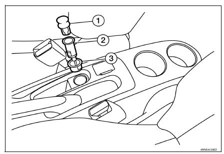
1. Cap 2. Inner socket 3. Ring
Removal and Installation
CONSOLE POWER SOCKET
Removal
1. Remove the fuse for the power socket.
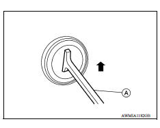
2. Insert one end of the Tool (A) into one of the square holes inside the power socket.
Tool number: - (J-42059)
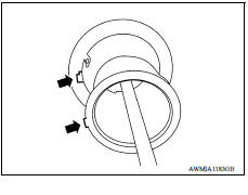
3. Lift up the handle of the Tool until the other end of the Tool is inside the socket and snaps into the other square hole in the power socket.
4. Pull the power socket straight out with the Tool.
5. Disconnect harness connector from power socket.
Installation
Installation is in the reverse order of removal.
NOTE: Make sure to align the tab with the square notched area during installation.
SERVICE DATA AND SPECIFICATIONS (SDS)
Power Socket 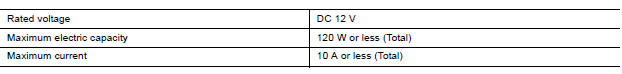
 Precautions
Precaution for Supplemental Restraint System (SRS) "AIR BAG" and "SEAT BELT PRE-TENSIONER" The Supplemental Restraint System such as "AIR BAG" and "SEAT BELT PRE-TENSIONER", us ...
Precautions
Precaution for Supplemental Restraint System (SRS) "AIR BAG" and "SEAT BELT PRE-TENSIONER" The Supplemental Restraint System such as "AIR BAG" and "SEAT BELT PRE-TENSIONER", us ...
Other materials:
NISSAN Voice Recognition System (if so equipped)
The NISSAN Voice Recognition system allows
hands-free operation of the systems equipped on
this vehicle, such as the phone and navigation
systems.
To operate NISSAN Voice Recognition, press
the button located on the steering
wheel.
When prompted, speak the command for the
system you wi ...
Fuel efficient driving tips
Follow these easy-to-use Fuel Efficient Driving
Tips to help you achieve the most fuel economy
from your vehicle.
1. Use Smooth Accelerator and Brake
Pedal Application
Avoid rapid starts and stops.
Use smooth, gentle accelerator and
brake application whenever possible.
Maintain constan ...
Categories
- Manuals Home
- Nissan Versa Owners Manual
- Nissan Versa Service Manual
- Video Guides
- Questions & Answers
- External Resources
- Latest Updates
- Most Popular
- Sitemap
- Search the site
- Privacy Policy
- Contact Us

0.0046