
Nissan Versa (N17): Rear door speaker
Diagnosis Procedure
Regarding Wiring Diagram information, refer to AV "Wiring Diagram".
1.CONNECTOR CHECK
Check the audio unit and speaker connectors for the following:
- Proper connection.
- Damage.
- Disconnected or loose terminals.
Is the inspection result normal?
YES >> GO TO 2.
NO >> Repair the terminals and connectors.
2.CHECK REAR DOOR SPEAKER SIGNAL CIRCUIT CONTINUITY
1. Disconnect audio unit connector M43 and suspect rear door speaker connector.
2. Check continuity between audio unit connector M43 and suspect rear door
speaker connector.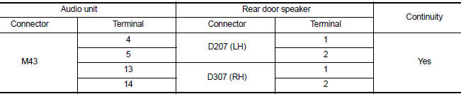
3. Check continuity between audio unit connector M43 and ground.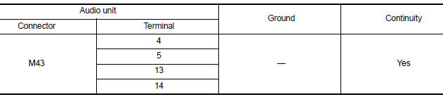
Is the inspection result normal?
YES >> GO TO 3
NO >> Repair harness or connector.
3.CHECK REAR DOOR SPEAKER SIGNAL
1. Connect audio unit connector M43 and suspect rear door speaker connector.
2. Turn ignition switch to ACC.
3. Push audio unit POWER switch.
4. Check signal between terminals of audio unit connector M43.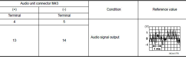
Is the inspection result normal?
YES >> Replace rear door speaker. Refer to AV "Removal and Installation".
NO >> Replace audio unit. Refer to AV "Removal and Installation".
SYMPTOM DIAGNOSIS
AUDIO SYSTEM
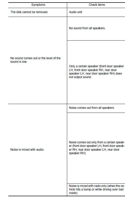
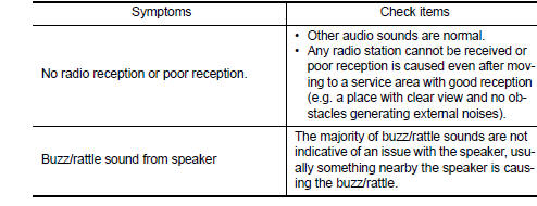
Symptom Table
RELATED TO AUDIO
 Front door speaker
Diagnosis Procedure Regarding Wiring Diagram information, refer to AV "Wiring Diagram". 1.CONNECTOR CHECK Check the audio unit and speaker connectors for the following: Proper conne ...
Normal operating condition
Description The majority of the audio troubles are the result of outside causes (bad CD, electromagnetic interference, etc.). NOISE The following noise results from variations in field strengt ...
Other materials:
Power outlets
Instrument panel
Console (if so equipped)
The power outlets are for powering electrical
accessories such as cellular telephones. The
outlets are rated at 12 volt, 120W (10A) maximum.
CAUTION
The outlet and plug may be hot during
or immediately after use.
Only certain power outlets ...
Key interlock cable
Exploded View
1. A/T shift selector assembly 2. Key interlock cable A: Key cylinder
B: Lock plate C: Clip
Removal and Installation
CAUTION:
Always apply the parking brake before performing removal and installation.
REMOVAL
Move the shift selector to the "N" position.
Remove the s ...
Categories
- Manuals Home
- Nissan Versa Owners Manual
- Nissan Versa Service Manual
- Video Guides
- Questions & Answers
- External Resources
- Latest Updates
- Most Popular
- Sitemap
- Search the site
- Privacy Policy
- Contact Us

0.006