Nissan Versa (N17): Roof side molding
Exploded View
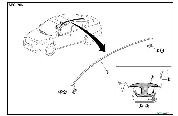
1. Roof side molding 2. Roof side molding clip 3. Roof panel 4. Body side outer panel
Removal and Installation
REMOVAL
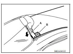
1. Release roof side molding clip using a suitable tool (A).
 : Clip
CAUTION: Apply protective tape (B) on body to protect the painted surface from damage.
2. Remove roof side molding, starting from the front of vehicle and moving toward the rear.
CAUTION: Do not pull the roof side molding with too much force.
INSTALLATION
Installation is in the reverse order of removal.
REMOVAL AND INSTALLATION OF ROOF SIDE MOLDING CLIP
Removal
1. Remove roof side molding.
2. Heat adhesive tape interface using a dryer and then peel roof side molding clips (body side) using a suitable tool.
CAUTION: Be careful not to damage the body.
Installation
1. Clean tape removed surface with a shop cloth soaked in white gasoline or IPA.
2. Use two-part epoxy adhesive.
Adhesive : 3M-weld DP-100 or equivalent
3. Apply adhesive evenly to clip tape surface.
Thickness : Approximately 0.5 mm (0.020 in)
4. Position applied parts to the proper location, and then sufficiently press-fit until the adhesive protrudes to tape side.
Press-fit limit : 19.6 N (2.0 Kg - 4.41 lb) × 2 seconds
5. Tape clips after press fit, and temporarily hold it for specified time based on the following.
5 to 10 C (41 to 50 F) : 1 hour or more
11 to 23 C (52 to 73 F) : 30 minutes or more
24 C or more (75 F or more) : 15 minutes or more
6. Install roof side molding from rear of vehicle to front, in this order after temporarily holding.
CAUTION:
- Use double-sided tape after hardening for clips.
- Securely insert molding rear end cap onto roof rear end cutout (installation standard).
- When installing roof side molding of windshield portion, check that molding fastener is securely inserted and then press in.
- Do not wash the vehicle within 24 hours so as to keep adhesive dry.
 Fender protector
Exploded View 1. Fender protector 2. J-nut Front Removal and Installation REMOVAL 1. Remove under cover. Refer to EXT"Removal and Installation". 2. Remove fender protector screws an ...
Door outside molding
Exploded View 1. Front door panel 2. Rear door panel 3. Front door outside molding 4. Rear door outside molding Pawl Removal and Installation FRONT DOOR OUTSIDE MOLDING Removal 1. Open fro ...
Other materials:
Thermostat
Exploded View
1. Radiator hose (lower) 2. Water inlet 3. Rubber ring
4. Thermostat A. To radiator
Removal and Installation
WARNING:
Do not remove the radiator cap when the engine is hot. Serious burns
could occur from highpressure
engine coolant escaping from the radiator. Wrap a thick cl ...
Exhaust valve timing control
Exhaust valve timing control : system diagram
Exhaust valve timing control : system description
INPUT/OUTPUT SIGNAL CHART
Sensor
Input signal to ECM
ECM function
Actuator
Crankshaft position sensor (POS)
Engine speed*1
Piston position
Exhaust valve timing c ...
Categories
- Manuals Home
- Nissan Versa Owners Manual
- Nissan Versa Service Manual
- Video Guides
- Questions & Answers
- External Resources
- Latest Updates
- Most Popular
- Sitemap
- Search the site
- Privacy Policy
- Contact Us

0.0061