Nissan Versa (N17): STRG Branch line circuit
Diagnosis Procedure
1.CHECK CONNECTOR
1. Turn the ignition switch OFF.
2. Disconnect the battery cable from the negative terminal.
3. Check the terminals and connectors of the steering angle sensor for damage, bend and loose connection (unit side and connector side).
Is the inspection result normal?
YES >> GO TO 2.
NO >> Repair the terminal and connector.
2.CHECK HARNESS FOR OPEN CIRCUIT
1. Disconnect the connector of steering angle sensor.
2. Check the resistance between the steering angle sensor harness connector
terminals.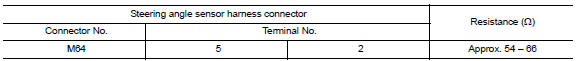
Is the measurement value within the specification?
YES >> GO TO 3.
NO >> Repair the steering angle sensor branch line.
3.CHECK POWER SUPPLY AND GROUND CIRCUIT
Check the power supply and the ground circuit of the steering angle sensor. Refer to BRC "Wiring Diagram".
Is the inspection result normal?
YES (Present error)>>Replace the steering angle sensor. Refer to BRC "Removal and Installation".
YES (Past error)>>Error was detected in the steering angle sensor branch line.
NO >> Repair the power supply and the ground circuit.
 M&A Branch line circuit
Diagnosis Procedure 1.CHECK CONNECTOR 1. Turn the ignition switch OFF. 2. Disconnect the battery cable from the negative terminal. 3. Check the terminals and connectors of the combination meter ...
BCM Branch line circuit
Diagnosis Procedure 1.CHECK CONNECTOR 1. Turn the ignition switch OFF. 2. Disconnect the battery cable from the negative terminal. 3. Check the terminals and connectors of the BCM for damage, bend ...
Other materials:
Secondary speed sensor
Exploded View
1. Transaxle assembly 2. O-ring 3. Secondary speed sensor
Front :
Genuine NISSAN CVT Fluid NS-3
Removal and Installation
REMOVAL
Remove the front LH wheel and tire. Refer to WT "Adjustment".
Remove the fender protector (LH). Refer to EXT "Removal and
...
Rear parcel shelf finisher
Exploded View
1. High-mounted stop lamp 2. Rear parcel shelf finisher 3. Seat belt finisher
4. Seatback latch cover 5. Top tether strap anchor 6. Top tether strap anchor
finisher
Front
Pawl
Removal and Installation
REMOVAL
Remove high-mounted stop lamp. Refer to EXL "Removal ...
Categories
- Manuals Home
- Nissan Versa Owners Manual
- Nissan Versa Service Manual
- Video Guides
- Questions & Answers
- External Resources
- Latest Updates
- Most Popular
- Sitemap
- Search the site
- Privacy Policy
- Contact Us

0.0046