Nissan Versa (N17): System
CHARGING SYSTEM
CHARGING SYSTEM : System Diagram
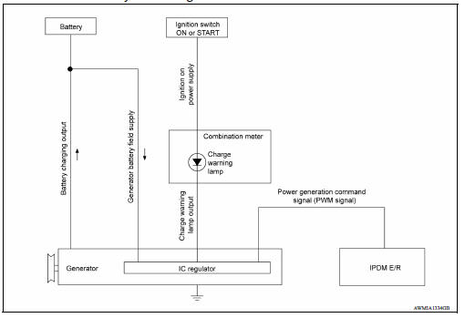
CHARGING SYSTEM : System Description
The generator provides DC voltage to operate the vehicle's electrical system and to keep the battery charged.
The voltage output is controlled by the IC regulator.
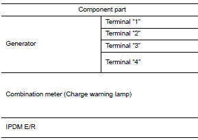
CHARGING SYSTEM : Component Description
POWER GENERATION VOLTAGE VARIABLE CONTROL SYSTEM
System Diagram
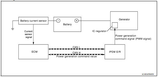
System Description
Power generation variable voltage control system has been adopted. By varying the voltage to the generator, engine load due to power generation of the generator is reduced and fuel consumption is decreased.
NOTE: When any malfunction is detected in the power generation variable voltage control system, power generation is performed according to the characteristic of the IC regulator in the generator.
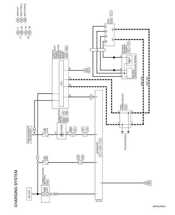
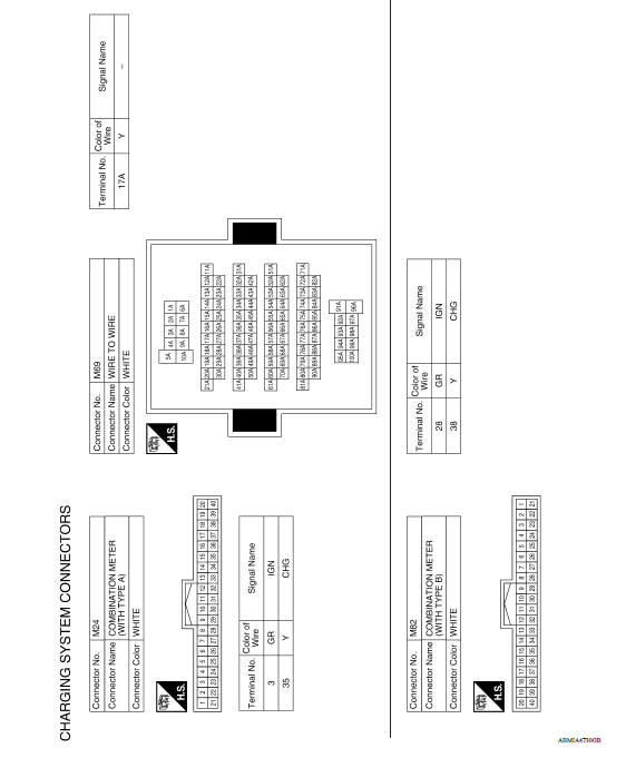
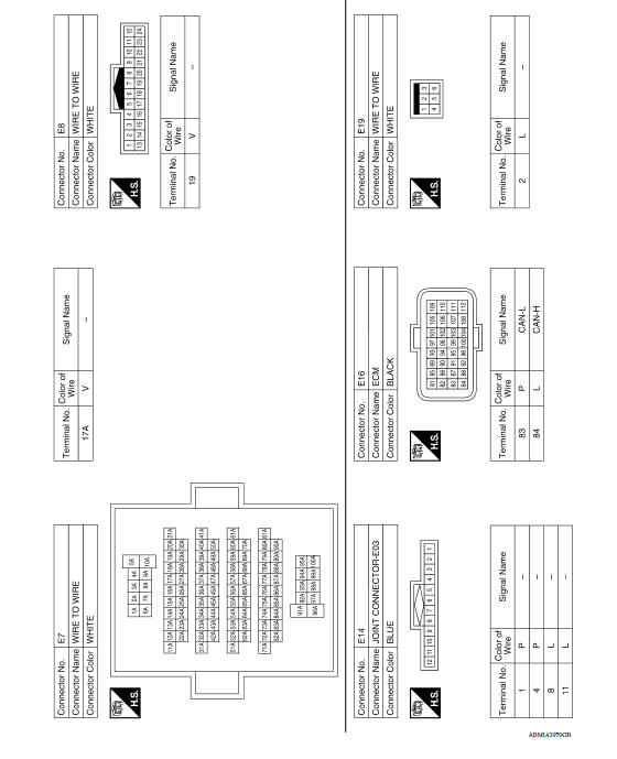
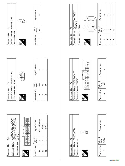
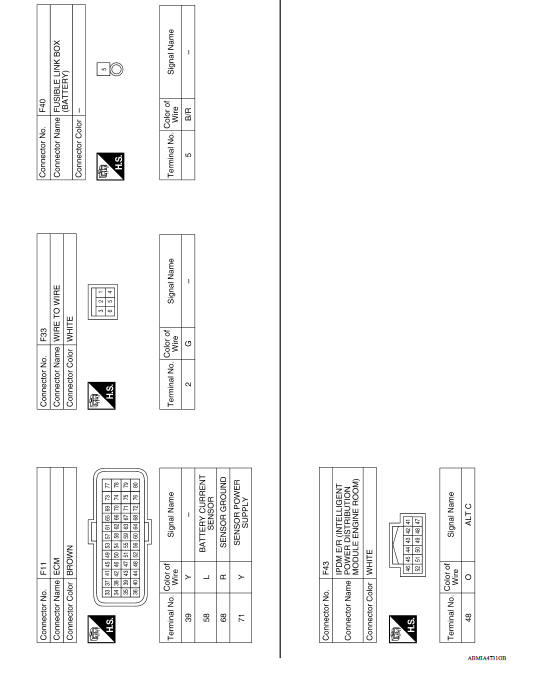
WIRING DIAGRAM
CHARGING SYSTEM
Wiring Diagram
BASIC INSPECTION
 Precautions
Precaution for Supplemental Restraint System (SRS) "AIR BAG" and "SEAT BELT PRE-TENSIONER" The Supplemental Restraint System such as "AIR BAG" and "SEAT BELT PRE-TENSIONER", us ...

Other materials:
Fuel-filler door
Opener operation
The fuel-filler door release is located below the
instrument panel. To open the fuel-filler door, pull
the release. To lock, close the fuel-filler door
securely.
Fuel-filler cap
WARNING
Gasoline is extremely flammable and
highly explosive under certain conditions.
...
Installing front license plate
Use the following steps to mount the front license
plate:
Before mounting the license plate, confirm that
the following parts are enclosed in the plastic
bag:
License plate bracket
License plate bracket screws x 2
Screw grommets x 2
1. Hold the license plate bracket 1 and make
a ...
Categories
- Manuals Home
- Nissan Versa Owners Manual
- Nissan Versa Service Manual
- Video Guides
- Questions & Answers
- External Resources
- Latest Updates
- Most Popular
- Sitemap
- Search the site
- Privacy Policy
- Contact Us

0.0049