Nissan Versa (N17): Diagnosis system (combination meter)
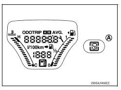
Type A
TYPE A : Diagnosis Description
ON BOARD DIAGNOSIS ITEM
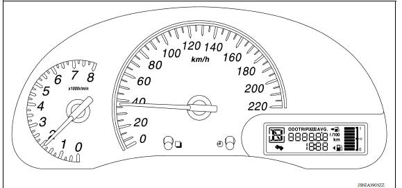
The information display, speedometer and tachometer can be checked in self-diagnosis mode.
NOTE:
- Check combination meter power supply and ground circuits if self-diagnosis mode does not start. Refer to MWI "COMBINATION METER : Diagnosis Procedure". Replace combination meter if power supply and ground circuits are found to be normal and self-diagnosis mode does not start. Refer to MWI "Removal and Installation".
- Combination meter self-diagnosis mode will function with the ignition switch in ON. Combination meter selfdiagnosis mode will exit upon turning the ignition switch to OFF.
METHOD OF STARTING
1. Turn the ignition switch OFF.
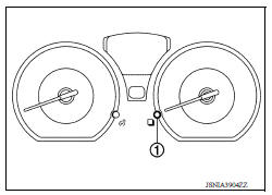
2. Turn the ignition switch ON while pressing and holding the switch (1) for 0.8 seconds or more.
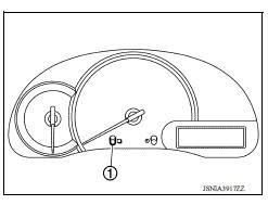
3. Press the  switch at least 3
times. (Within 7 seconds after the ignition switch is turned ON.)
switch at least 3
times. (Within 7 seconds after the ignition switch is turned ON.)
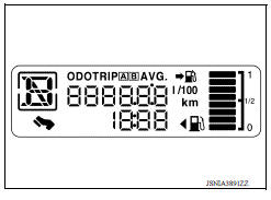
4. The combination meter is turned to self-diagnosis mode.
- All segments of the information display are displayed.
5. Each meter activates by pressing the
switch.
NOTE:
- If any of the meters or gauges is not activated, replace combination meter.
- The figure is reference.
TYPE A : CONSULT Function
APPLICATION ITEMS
CONSULT can display each diagnostic item using the diagnostic test modes shown.
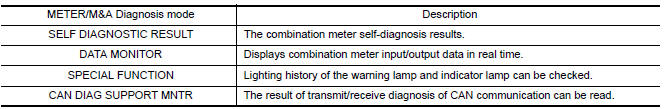
SELF DIAG RESULT
Refer to MWI "DTC Index".
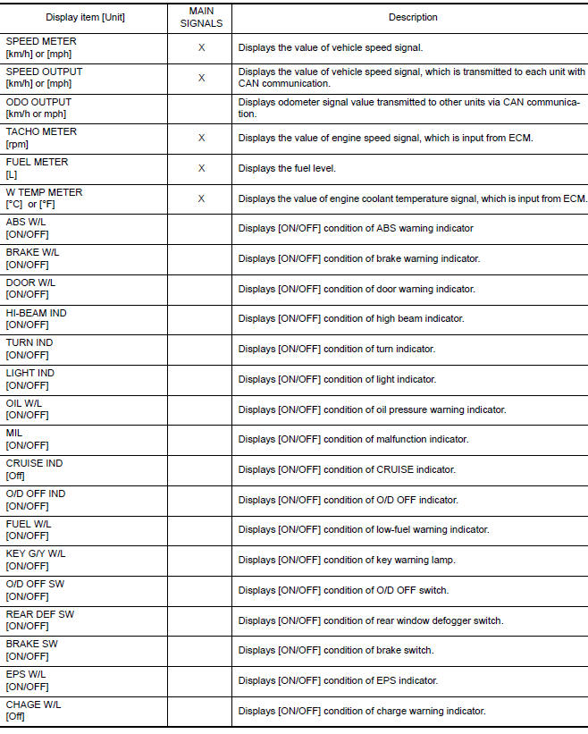
DATA MONITOR
Display Item List
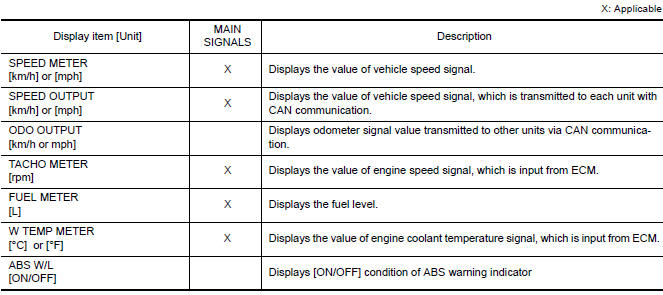
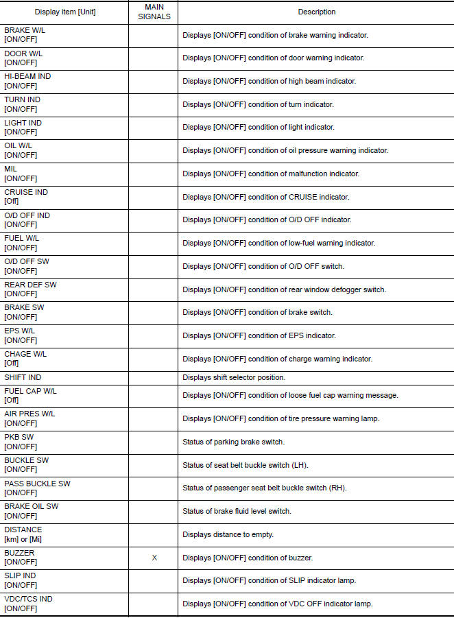
NOTE: Some items are not available according to vehicle specification.
SPECIAL FUNCTION
Special menu

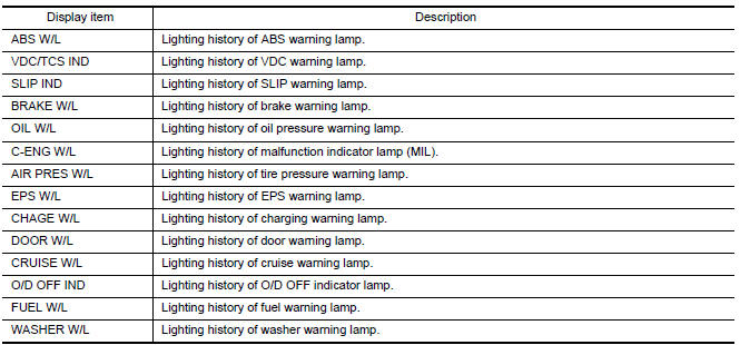
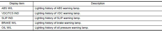
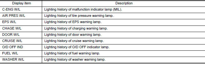
W/L ON HISTORY
- Stores histories when warning/indicator lamp is turned on.
- "W/L ON HISTORY" indicates the "TIME" when the warning/ indicator lamp is turned on.
- The "TIME" above is:
- 0: The condition that the warning/indicator lamp has been turned on 1 or more times after starting the engine and waiting for 30 seconds.
- 1 - 39: The number of times the engine was restarted after the 0 condition.
- NO W/L ON HISTORY: Stores NO (0) turning on history of warning/indicator lamp.
NOTE:
- W/L ON HISTORY is not stored for approximately 30 seconds after the engine starts.
- Brake warning lamp does not store any history when the parking brake is applied or the brake fluid level gets low.
Display Item
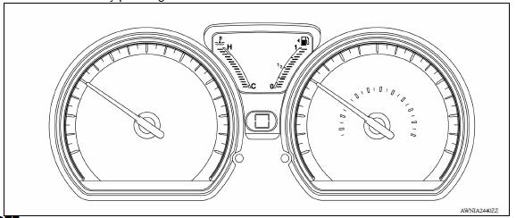
Type B
TYPE B : Diagnosis Description
COMBINATION METER SELF-DIAGNOSIS MODE
The information display, speedometer and tachometer can be checked in self-diagnosis mode.
STARTING COMBINATION METER SELF-DIAGNOSIS MODE
NOTE:
- Check combination meter power supply and ground circuits if self-diagnosis mode does not start. Refer to MWI "COMBINATION METER : Diagnosis Procedure". Replace combination meter if power supply and ground circuits are found to be normal and self-diagnosis mode does not start. Refer to MWI "Removal and Installation".
- Combination meter self-diagnosis mode will function with the ignition switch in ON. Combination meter selfdiagnosis mode will exit upon turning the ignition switch to OFF.
How to Initiate Self-Diagnosis Mode
1. Turn ignition switch ON, press the odo/trip meter switch (1) to "trip A" or "trip B".
2. Turn ignition switch to OFF.
3. Continue holding the odo/trip meter switch (1) and turn the ignition switch ON.
4. Verify the trip meter displays "0000.0".
5. Press the meter control switch at least 3 times. (Within 7 seconds after the ignition switch is turned ON).
6. The combination meter self-diagnosis mode is activated.
- Verify all segments of the information display and shift position indicator (A) for CVT models are displayed.
7. Each meter activates by pressing the meter control switch.
NOTE:
- If any of the meters or gauges is not activated, replace combination meter.
- The figure is reference.
TYPE B : CONSULT Function
APPLICATION ITEMS
CONSULT can display each diagnostic item using the diagnostic test modes
shown.

SELF DIAG RESULT
Refer to MWI "DTC Index".
DATA MONITOR
Display Item List

NOTE: Some items are not available according to vehicle specification.
SPECIAL FUNCTION
Special menu

W/L ON HISTORY
- Stores histories when warning/indicator lamp is turned on.
- "W/L ON HISTORY" indicates the "TIME" when the warning/ indicator lamp is turned on.
- The "TIME" above is:
- 0: The condition that the warning/indicator lamp has been turned on 1 or more times after starting the engine and waiting for 30 seconds.
- 1 - 39: The number of times the engine was restarted after the 0 condition.
- NO W/L ON HISTORY: Stores NO (0) turning on history of warning/indicator lamp.
NOTE:
- W/L ON HISTORY is not stored for approximately 30 seconds after the engine starts.
- Brake warning lamp does not store any history when the parking brake is applied or the brake fluid level gets low.
Display Item
DIAGNOSIS SYSTEM (BCM) (WITH INTELLIGENT KEY SYSTEM)
COMMON ITEM
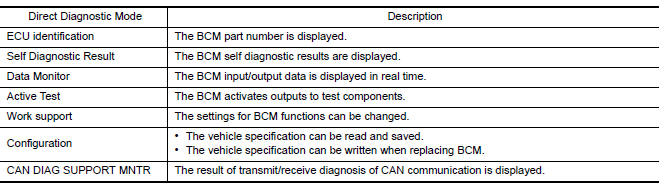
COMMON ITEM : CONSULT Function (BCM - COMMON ITEM)
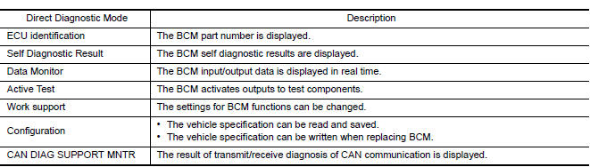
APPLICATION ITEM
CONSULT performs the following functions via CAN communication with BCM.
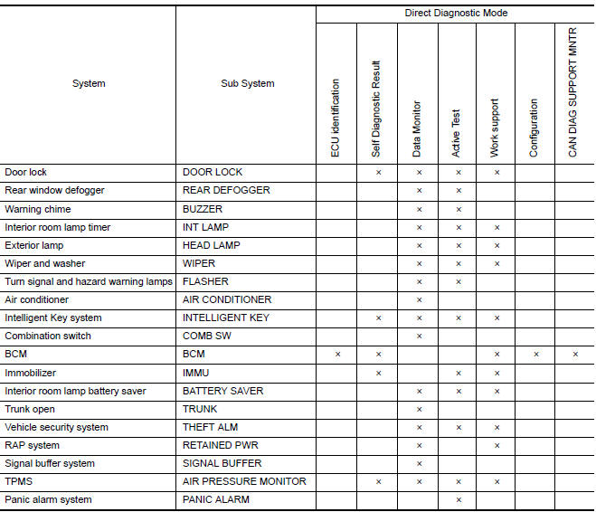
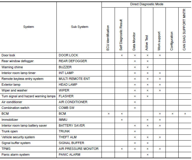
SYSTEM APPLICATION
BCM can perform the following functions.
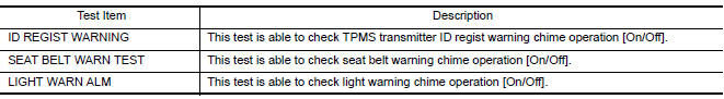
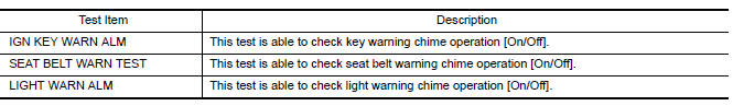
BUZZER
BUZZER : CONSULT Function (BCM - BUZZER)
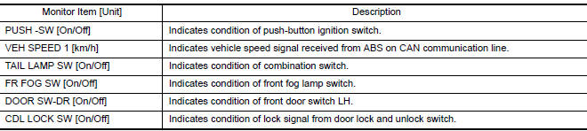
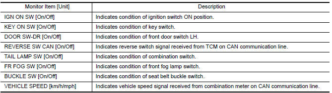
DATA MONITOR
ACTIVE TEST
DIAGNOSIS SYSTEM (BCM) (WITHOUT INTELLIGENT KEY SYSTEM)
COMMON ITEM
COMMON ITEM : CONSULT Function (BCM - COMMON ITEM)
APPLICATION ITEM
CONSULT performs the following functions via CAN communication with BCM.
SYSTEM APPLICATION
BCM can perform the following functions.
BUZZER
BUZZER : CONSULT Function (BCM - BUZZER)
DATA MONITOR
ACTIVE TEST
ECU DIAGNOSIS INFORMATION
BCM, COMBINATION METER
List of ECU Reference
| ECU | Reference |
| BCM (with Intelligent Key) | BCS "Reference Value" |
| BCS "Fail-safe" | |
| BCS "DTC Inspection Priority Chart" | |
| BCS "DTC Index" | |
| BCM (without Intelligent Key) | BCS "Reference Value" |
| BCS "Fail-safe" | |
| BCS "DTC Inspection Priority Chart" | |
| BCS "DTC Index" | |
| COMBINATION METER (TYPE A) | MWI"Reference Value" |
| MWI "Fail-Safe" | |
| MWI "DTC Index" | |
| COMBINATION METER (TYPE B) | MWI"Reference Value" |
| MWI "Fail-Safe" | |
| MWI "DTC Index" |
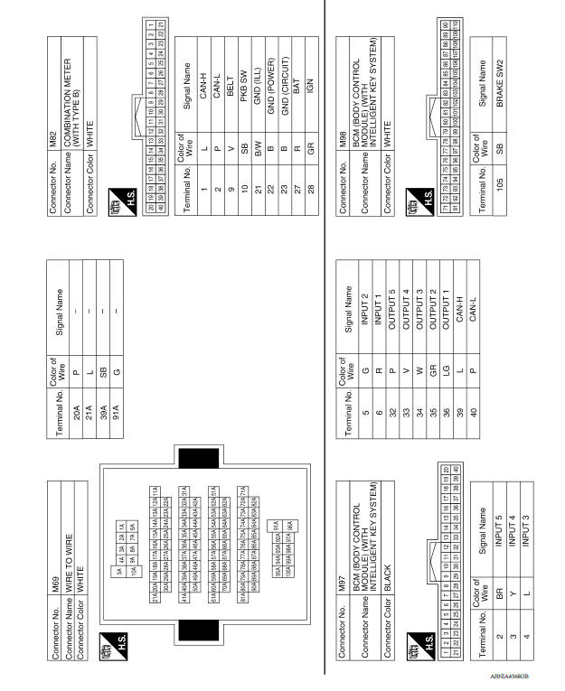
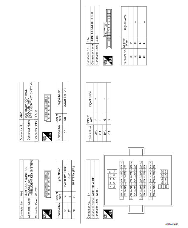
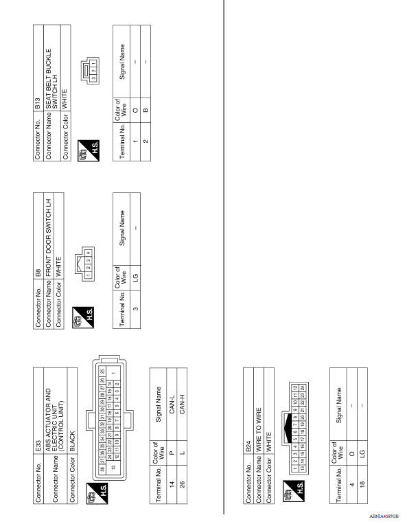
WIRING DIAGRAM
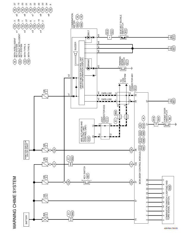
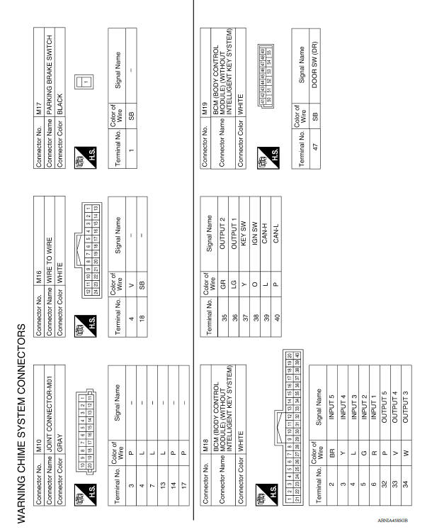
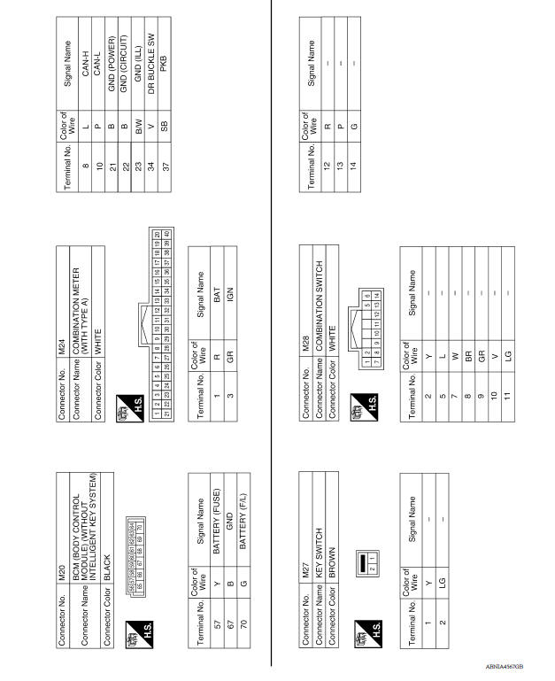
WARNING CHIME SYSTEM
Wiring Diagram
BASIC INSPECTION
 System
Diagnosis and repair workflow
Work Flow OVERALL SEQUENCE DETAILED FLOW 1.OBTAIN INFORMATION ABOUT SYMPTOM Interview the customer to obtain as much information as possible about the conditions and environment under whic ...
Other materials:
Water pump
Exploded View
1. Gasket 2. Water pump 3. Water pump pulley
Removal and Installation
REMOVAL
CAUTION:
Do not remove the radiator cap when the engine is hot. Serious burns
could occur from highpressure
engine coolant escaping from the radiator. Wrap a thick cloth around the
radiator cap. ...
Key id warning does not operate
Diagnosis Procedure
1.CHECK DTC WITH BCM
Check that DTC is not detected with BCM
Is the inspection result normal?
YES >> GO TO 2.
NO >> Perform trouble diagnosis relevant to DTC indicated.
2.CHECK DTC WITH COMBINATION METER
Check that DTC is not detected with combination meter
...
Categories
- Manuals Home
- Nissan Versa Owners Manual
- Nissan Versa Service Manual
- Video Guides
- Questions & Answers
- External Resources
- Latest Updates
- Most Popular
- Sitemap
- Search the site
- Privacy Policy
- Contact Us

0.0066