Nissan Versa (N17): U1000 CAN COMM
DTC Logic
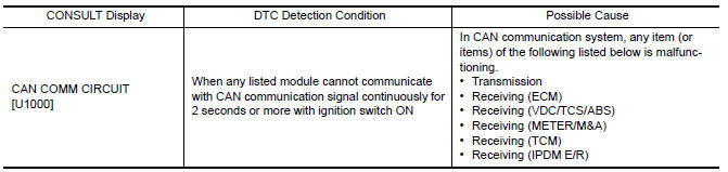
DTC DETECTION LOGIC
NOTE: U1000 can be set if a module harness was disconnected and
reconnected, perhaps during a repair. Confirm that there are actual CAN
diagnostic symptoms and a present DTC by performing the Self Diagnostic Result
procedure.
Diagnosis Procedure
1. PERFORM SELF DIAGNOSTIC RESULT
- Turn ignition switch ON and wait for 2 second or more.
- Check "SELF- DIAG RESULTS".
Is "CAN COMM CIRCUIT" displayed?
YES >> Perform CAN Diagnosis as described in DIAGNOSIS section of CONSULT Operation manual.
NO >> Refer to GI "Intermittent Incident".
U1010 CONTROL UNIT (CAN)
DTC Logic
DTC DETECTION LOGIC 
Diagnosis Procedure
1.REPLACE BCM
When DTC "U1010" is detected, replace BCM.
>> Replace BCM. Refer to BCS "Removal and Installation".
 Diagnosis and repair workflow
Work Flow OVERALL SEQUENCE DETAILED FLOW 1.GET INFORMATION FOR SYMPTOM Get the detailed information from the customer about the symptom (the condition and the environment when the incident/ ...
Power supply and ground circuit
Diagnosis Procedure Regarding Wiring Diagram information, refer to BCS "Wiring Diagram". 1.CHECK FUSES AND FUSIBLE LINK Check that the following fuses and fusible link are not blown. ...
Other materials:
How to select piston and bearing
Description
Selection points
Selection parts
Selection items
Selection methods
Between cylinder block and
crankshaft
Main bearing
Main bearing grade (bearing
thickness)
Determined by match of cylinder
block bearing housing
grade (inner diameter of housi ...
Trunk lid trim
Exploded View
1. Trunk lid assembly 2. Trunk lid finisher
Removal and Installation
REMOVAL
Fully open trunk lid.
Remove emergency release handle. Refer to DLK "EMERGENCY LEVER : Removal
and Installation".
Disconnect the harness connector (A) from the trunk lid lock
as ...
Categories
- Manuals Home
- Nissan Versa Owners Manual
- Nissan Versa Service Manual
- Video Guides
- Questions & Answers
- External Resources
- Latest Updates
- Most Popular
- Sitemap
- Search the site
- Privacy Policy
- Contact Us

0.0049