Nissan Versa (N17): Vacuum lines
Exploded View
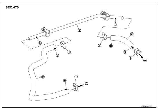
1. Clamp 2. Vacuum hose 3. Vacuum piping A. To brake booster B. Paint mark C. To intake manifold
Removal and Installation
REMOVAL
- Remove the air cleaner and duct assembly. Refer to EM "Exploded View".
- Remove the vacuum hose and vacuum piping.
INSTALLATION
Installation is in the reverse order of removal.
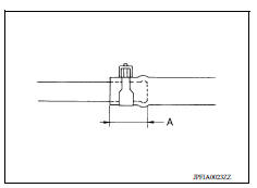
- When installing vacuum hose, insert it until its tip reaches the
back-end of length (A) or further as shown.
CAUTION: Do not use lubricating oil during assembly.
(A) : 24 mm (0.95 in) or more
- Face the paint mark of vacuum hose (intake manifold side) upward to assemble.
- Face the other paint marks of vacuum hose to the vehicle front side to assemble.
Inspection
INSPECTION AFTER REMOVAL
Appearance
Check for correct assembly, damage and deterioration.
FRONT DISC BRAKE
 Brake booster and check valve
Exploded View 1. Master cylinder assembly 2. Check valve 3. Brake booster 4. Lock nut 5. Clevis 6. Gasket ...
Brake pad
BRAKE PAD : Exploded View 1. Cylinder body 2. Inner shim 3. Inner pad (with pad wear sensor) 4. Pad return spring 5. Pad retainer 6. Torque member 7. Outer pad 8. Outer shim : Apply MOLYKOTE 7 ...
Other materials:
P0506 ISC system
Description
The ECM controls the engine idle speed to a specified level through the fine
adjustment of the air, which is let
into the intake manifold, by operating the electric throttle control actuator.
The operating of the throttle valve is
varied to allow for optimum control of the engine ...
Occupant classification system
OCCUPANT CLASSIFICATION SYSTEM : System Diagram
OCCUPANT CLASSIFICATION SYSTEM : System
Description
The occupant classification system (OCS) identifies different size occupants,
out of position occupants, and
detects if child seat is present in the front passenger seat. The OCS control
...
Categories
- Manuals Home
- Nissan Versa Owners Manual
- Nissan Versa Service Manual
- Video Guides
- Questions & Answers
- External Resources
- Latest Updates
- Most Popular
- Sitemap
- Search the site
- Privacy Policy
- Contact Us

0.0053