Nissan Versa (N17): VDC OFF Switch
Component Function Check
1.CHECK VDC OFF SWITCH OPERATION
Check that VDC OFF indicator lamp in combination meter turns ON/OFF when VDC OFF switch is operated.
Is the inspection result normal?
YES >> Inspection End.
NO >> Proceed to diagnosis procedure. Refer to BRC "Diagnosis Procedure".
Diagnosis Procedure
Regarding Wiring Diagram information, refer to BRC "Wiring Diagram".
1.CONNECTOR INSPECTION
- Turn ignition switch OFF.
- Disconnect ABS actuator and electric unit (control unit) and VDC OFF switch connectors.
- Check connectors and terminals for deformation, disconnection, looseness or damage.
Is the inspection result normal?
YES >> GO TO 2
NO >> Repair or replace as necessary.
2.CHECK VDC OFF SWITCH
Check VDC OFF switch. Refer to BRC "Component Inspection".
Is the inspection result normal?
YES >> GO TO 3.
NO >> Replace VDC OFF switch. Refer to BRC "Removal and Installation".
3.CHECK VDC OFF SWITCH SIGNAL
With CONSULT.
- Connect ABS actuator and electric unit (control unit) and VDC OFF switch connectors.
- Turn ignition switch ON.
- In "DATA MONITOR" select "OFF SW" and check VDC OFF switch signal.
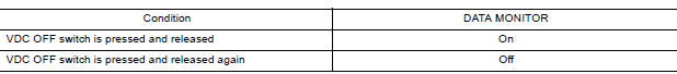
Is the inspection result normal?
YES >> Refer to BRC "Work Flow".
NO >> GO TO 4.
4.CHECK VDC OFF SWITCH CIRCUIT
- Turn ignition switch OFF.
- Disconnect ABS actuator and electric unit (control unit) and VDC OFF switch connectors.
- Check continuity between ABS actuator and electric unit (control unit)
connector E33 terminal 15 and
VDC OFF switch connector M34 terminal 1.

4. Check continuity between ABS actuator and
electric unit (control unit) connector terminal E33 terminal 15
and ground. 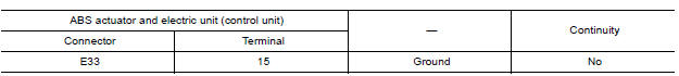
Is the inspection result normal?
YES >> GO TO 5.
NO >> Repair or replace malfunctioning components.
5.CHECK VDC OFF SWITCH GROUND CIRCUIT
Check continuity between VDC OFF switch connector M34 terminal 2 and ground. 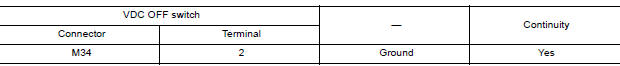
Is the inspection result normal?
YES >> Replace ABS actuator and electric unit (control unit). Refer to BRC "Removal and Installation".
NO >> Repair or replace malfunctioning components.
Component Inspection
1.CHECK VDC OFF SWITCH
- Turn ignition switch OFF.
- Disconnect VDC OFF switch connector.
- Check continuity between terminals of VDC OFF switch connector.
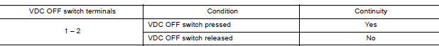
Is the inspection result normal?
YES >> Inspection End.
NO >> Replace VDC OFF switch. Refer to BRC "Removal and Installation".
 Parking brake switch
Component Function Check 1.CHECK PARKING BRAKE SWITCH OPERATION Check that brake warning lamp in combination meter turns ON/OFF when parking brake is actuated. Is the inspection result normal? ...
ABS Warning lamp
Component Function Check 1.CHECK ABS WARNING LAMP FUNCTION Check that ABS warning lamp in combination meter turns ON for approximately 2 seconds after ignition switch is turned ON. Is the insp ...
Other materials:
Cylinder block
Exploded View
1. Crankshaft position sensor cover 2. Crankshaft position sensor (POS) 3.
Oring
4. Drain plug 5. Cylinder block 6. Oil level gauge
7. Oil level gauge guide 8. Oring 9. Knock sensor 10. Oil temperature sensor
11. Oil pressure sensor 12. Oil jet
13. Top ring 14. Second ring ...
Hazard function
Component Function Check
1.CHECK FUNCTION
Select INTELLIGENT KEY of BCM using CONSULT.
Select FLASHER in ACTIVE TEST mode.
Touch LH or RH to check that it works normally.
Is the inspection result normal?
YES >> Hazard warning lamp circuit is OK.
NO >> Refer to DLK "D ...
Categories
- Manuals Home
- Nissan Versa Owners Manual
- Nissan Versa Service Manual
- Video Guides
- Questions & Answers
- External Resources
- Latest Updates
- Most Popular
- Sitemap
- Search the site
- Privacy Policy
- Contact Us

0.0062