Nissan Versa (N17): Wiper arm
Wiper arm: Removal and Installation
REMOVAL
1. Operate wiper to move it to the auto stop position.
2. Fully open hood assembly.
3. Remove wiper arm caps.
4. Remove wiper arm nuts.
5. Raise wiper arm and remove wiper arm from the vehicle.
INSTALLATION
1. Clean wiper arm mount as shown.
NOTE: This will reduce the possibility of wiper arm looseness.
2. Operate wiper motor to move the wiper to the auto stop position.
3. Install wiper arm to wiper drive assembly. Temporarily tighten nut.
4. Adjust wiper blade position. Refer to WW "WIPER ARM : Adjustment".
5. Tighten wiper arm nuts to specification.
6. Operate wiper to move it to the auto stop position.
CAUTION: Before operating wiper, spray washer fluid so that windshield glass damage by wiper operation is prevented.
7. Check that wiper blades stop at the specified position.
8. Install wiper arm caps.
Wiper arm : Adjustment
WIPER BLADE POSITION ADJUSTMENT
Clearance between the end of cowl top cover/ front fender cover and the top of wiper blade center
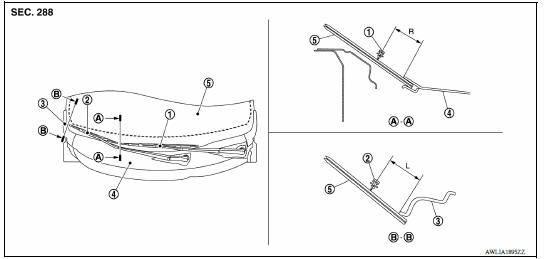
1. Wiper blade (LH) 2. Wiper blade (RH) 3. Front fender cover (RH) 4. Cowl top cover 5. Windshield glass
Standard clearance
R : 44.2 +- 7.5 mm (1.74 +- 0.30 in)
L : 67.1 +- 7.5 mm (2.64 +- 0.30 in)
 Normal operating condition
Description FRONT WIPER PROTECTION FUNCTION IPDM E/R detects front wiper stop position by a front wiper stop position signal. When a front wiper stop position signal is in the conditions list ...
Wiper blade
WIPER BLADE : Removal and Installation REMOVAL 1. Lift up wiper arm and set to the position where wiper arm can be locked back. 2. Press and hold lever (A) of wiper blade (1). Pull in the direc ...
Other materials:
P0980 Shift solenoid C
DTC Logic
DTC DETECTION LOGIC
DTC
Trouble diagnosis name
DTC detection condition
Possible causes
P0980
Shift Solenoid C Control Circuit
High
The following diagnosis conditions
are met, and the TCM 2-4
brake solenoid valve current
monitor reading is 200 mA ...
Output speed sensor
Exploded View
1. Output speed sensor 2. O-ring 3. Transaxle assembly
Front
Removal and Installation
REMOVAL
Remove the front LH wheel and tire.
Disconnect the harness connector from output speed sensor.
Remove the output speed sensor.
Remove the O-ring from the output speed sens ...
Categories
- Manuals Home
- Nissan Versa Owners Manual
- Nissan Versa Service Manual
- Video Guides
- Questions & Answers
- External Resources
- Latest Updates
- Most Popular
- Sitemap
- Search the site
- Privacy Policy
- Contact Us

0.0061