Nissan Versa (N17): Air cleaner filter
Exploded View
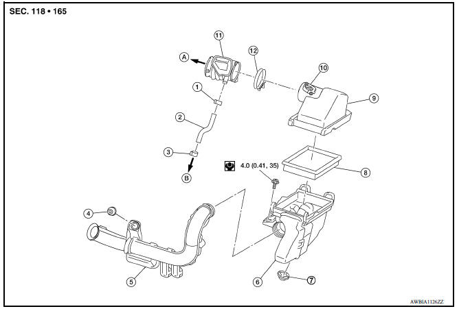
1. Clamp 2. PCV hose 3. Clamp 4. Mount rubber 5. Air duct (inlet) 6. Air cleaner body 7. Grommet 8. Air cleaner filter 9. Air cleaner cover 10. Mass air flow sensor 11. Air duct 12. Clamp
Removal and Installation
REMOVAL
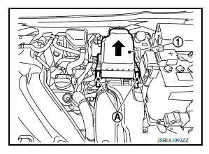
1. Unhook clips (A) and pull the air cleaner cover upward (1).
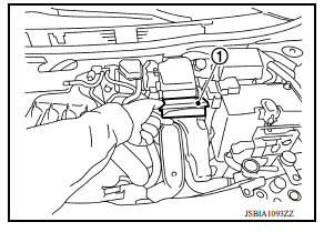
2. Remove the air cleaner filter (1) from the air cleaner body.
INSTALLATION
Installation is in the reverse order of removal.
NOTE:
Check that the air cleaner filter is securely placed in the air cleaner body.
 Drive belt
Exploded View 1. Generator 2. Water pump 3. Crankshaft pulley 4. A/C compressor (with A/C models) Idler pulley (without A/C models) 5. Idler pulley 6. Drive belt ...
Spark plug
Exploded View 1. Ignition coil 2. Spark plug Removal and Installation REMOVAL 1. Remove ignition coil. CAUTION: Do not drop or shock ignition coil. 2. Remove spark plug using a suitable tool. ...
Other materials:
Before starting the engine
Make sure the area around the vehicle is
clear.
Check fluid levels such as engine oil, coolant,
brake and clutch fluid (if so equipped),
and windshield-washer fluid as frequently as
possible, or at least whenever you refuel.
Check that all windows and lights are clean.
Visually insp ...
Hazard warning flasher switch
Push the switch on to warn other drivers when
you must stop or park under emergency conditions.
All turn signal lights flash.
WARNING
If stopping for an emergency, be sure to
move the vehicle well off the road.
Do not use the hazard warning flashers
while moving on the highway unl ...
Categories
- Manuals Home
- Nissan Versa Owners Manual
- Nissan Versa Service Manual
- Video Guides
- Questions & Answers
- External Resources
- Latest Updates
- Most Popular
- Sitemap
- Search the site
- Privacy Policy
- Contact Us

0.0065