Nissan Versa (N17): B2195 Anti-scanning
DTC Logic
DTC DETECTION LOGIC 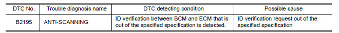
DTC CONFIRMATION PROCEDURE
1.PERFORM DTC CONFIRMATION PROCEDURE
1. Turn ignition switch ON.
2. Check DTC in Self Diagnostic Result mode of BCM using CONSULT.
Is DTC detected?
YES >> Refer to SEC "Diagnosis Procedure".
NO >> Inspection End.
Diagnosis Procedure
1.CHECK SELF DIAGNOSTIC RESULT 1
1. Select Self Diagnostic Result mode of BCM using CONSULT.
2. Erase DTC.
3. Perform DTC CONFIRMATION PROCEDURE for DTC B2195. Refer to SEC "DTC Logic".
Is DTC detected?
YES >> GO TO 2.
NO >> Inspection End.
2.CHECK EQUIPMENT OF THE VEHICLE
Check that unspecified accessory part related to engine start is not installed.
Is unspecified accessory part related to engine start installed?
YES >> GO TO 3.
NO >> GO TO 4.
3.CHECK SELF DIAGNOSTIC RESULT 2
1. Obtain the customers approval to remove unspecified accessory part related to engine start, and then remove it.
2. Select Self Diagnostic Result of BCM using CONSULT.
3. Erase DTC.
4. Perform DTC CONFIRMATION PROCEDURE for DTC B2195. Refer to SEC "DTC Logic".
Is DTC detected?
YES >> GO TO 4.
NO >> Inspection End.
4.REPLACE BCM
1. Replace BCM. Refer to BCS "Removal and Installation".
2. Perform initialization of BCM and registration of all Intelligent Keys using CONSULT.
>> Inspection End.
 B2193 Chain of ECM-IMMU
B2196 Dongle unit
Description BCM performs ID verification between BCM and dongle unit. When verification result is OK, BCM permits cranking. ...
Other materials:
Accelerator pedal released position
learning
Description
Accelerator Pedal Released Position Learning is a function of ECM to learn
the fully released position of the
accelerator pedal by monitoring the accelerator pedal position sensor output
signal. It must be performed each
time harness connector of accelerator pedal position senso ...
P072E Stuck in 3GR
DTC Logic
DTC DETECTION LOGIC
DTC
Trouble diagnosis name
DTC detection condition
Possible causes
P072E
Stuck in Gear 3
The following diagnosis conditions
are met and the detection
conditions continue for 0.5 seconds
or more.- Diagnosis condition
- Shifti ...
Categories
- Manuals Home
- Nissan Versa Owners Manual
- Nissan Versa Service Manual
- Video Guides
- Questions & Answers
- External Resources
- Latest Updates
- Most Popular
- Sitemap
- Search the site
- Privacy Policy
- Contact Us

0.0059