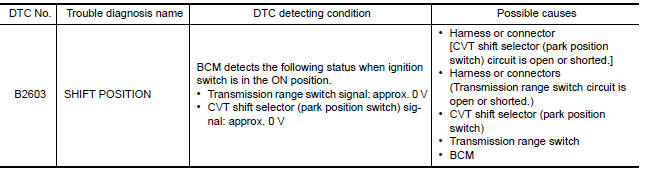
Nissan Versa (N17): B2603 Shift position
DTC Logic
DTC DETECTION LOGIC
NOTE: If DTC B2603 is displayed with DTC B2601, first perform the trouble
diagnosis for DTC B2601. Refer to
SEC "DTC Logic".
DTC CONFIRMATION PROCEDURE
1.PERFORM DTC CONFIRMATION PROCEDURE 1
1. Shift the selector lever to the P position.
2. Turn ignition switch ON and wait 1 second or more.
3. Check DTC in Self Diagnostic Result mode of BCM using CONSULT.
Is DTC detected?
YES >> Go to SEC "Diagnosis Procedure".
NO >> GO TO 2.
2.PERFORM DTC CONFIRMATION PROCEDURE 2
1. Shift the selector lever to the position other than P and N, and wait 1 second or more.
2. Check DTC in Self Diagnostic Result mode of BCM using CONSULT.
Is DTC detected?
YES >> Go to SEC "Diagnosis Procedure".
NO >> Inspection End.
Diagnosis Procedure
Regarding Wiring Diagram information, refer to SEC "Wiring Diagram".
1.INSPECTION START
Perform inspection in accordance with procedure that confirms DTC.
Which procedure confirms DTC?
DTC confirmation procedure 1>>GO TO 2.
DTC confirmation procedure 2>>GO TO 8.
2.CHECK FUSE
1. Turn power switch OFF.
2. Check that the following fuse in IPDM E/R is not blown. 
Is the inspection result normal?
YES >> GO TO 3.
NO >> Replace the blown fuse after repairing the cause of blowing.
3.CHECK TRANSMISSION RANGE SWITCH POWER SUPPLY
1. Disconnect transmission range switch connector.
2. Turn ignition switch ON.
3. Check voltage between transmission range switch harness connector and
ground. 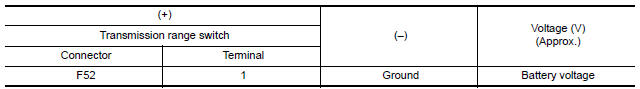
Is the inspection result normal?
YES >> GO TO 5.
NO >> GO TO 4.
4.CHECK TRANSMISSION RANGE SWITCH POWER SUPPLY CIRCUIT
1. Turn ignition switch OFF.
2. Disconnect IPDM E/R connector.
3. Check continuity between transmission range switch harness connector and
IPDM E/R harness connector.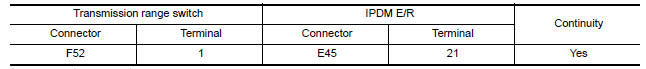
Is the inspection result normal?
YES >> Replace IPDM E/R. Refer to PCS "Removal and Installation".
NO >> Repair or replace harness.
5.CHECK BCM INPUT SIGNAL
1. Turn ignition switch OFF.
2. Connect transmission range switch harness connector.
3. Turn ignition switch ON.
4. Check voltage between BCM harness connector and ground. 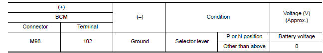
Is the inspection result normal?
YES >> GO TO 13.
NO >> GO TO 6.
6.CHECK BCM INPUT SIGNAL CIRCUIT
1. Turn ignition switch OFF.
2. Disconnect transmission range switch connector.
3. Disconnect BCM connector.
4. Check continuity between transmission range switch harness connector and
BCM harness connector.
Is the inspection result normal?
YES >> GO TO 7.
NO >> Repair or replace harness.
7.CHECK TRANSMISSION RANGE SWITCH
Refer to SEC "Component Inspection (Transmission Range Switch)".
Is the inspection result normal?
YES >> GO TO 12.
NO >> Replace transmission range switch.
8.CHECK CVT SHIFT SELECTOR POWER SUPPLY
1. Turn ignition switch OFF.
2. Disconnect CVT shift selector (park position switch) connector.
3. Check voltage between CVT shift selector (park position switch) harness
connector and ground.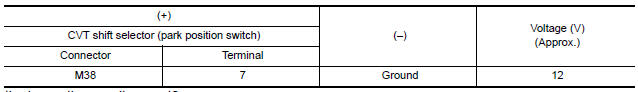
Is the inspection result normal?
YES >> GO TO 10.
NO >> GO TO 9.
9.CHECK CVT SHIFT SELECTOR POWER SUPPLY CIRCUIT
1. Disconnect BCM connector.
2. Check continuity between CVT shift selector (park position switch) harness
connector and BCM harness
connector.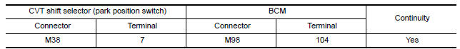
3. Check continuity between CVT shift selector (park position switch) harness
connector and ground. 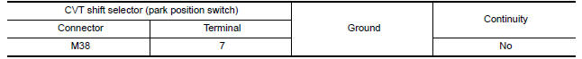
Is the inspection result normal?
YES >> GO TO 12.
NO >> Repair or replace harness.
10.CHECK CVT SHIFT SELECTOR CIRCUIT
1. Disconnect BCM connector.
2. Check continuity between CVT shift selector (park position switch) harness
connector and BCM harness
connector. 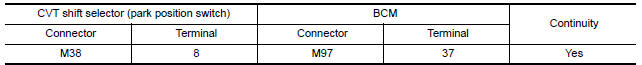
3. Check continuity between CVT shift selector (park position switch) harness
connector and ground.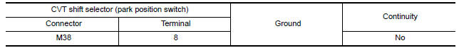
Is the inspection result normal?
YES >> GO TO 11.
NO >> Repair or replace harness.
11.CHECK CVT SHIFT SELECTOR (PARK POSITION SWITCH)
Refer to SEC "Component Inspection [CVT Shift Selector (Park Position Switch)]".
Is the inspection result normal?
YES >> GO TO 13.
NO >> Replace CVT shift selector. Refer to TM "Removal and Installation".
12.CHECK INTERMITTENT INCIDENT
Refer to GI "Intermittent Incident".
>> Inspection End.
13.REPLACE BCM
1. Replace BCM. Refer to BCS "Removal and Installation".
2. Perform initialization of BCM and registration of all Intelligent Keys using CONSULT.
>> Inspection End.
Component Inspection (Transmission Range Switch)
1.CHECK TRANSMISSION RANGE SWITCH
1. Turn ignition switch OFF.
2. Disconnect transmission range switch connector.
3. Check continuity between transmission range switch terminals. 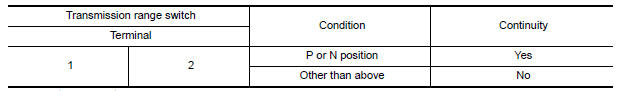
Is the inspection result normal?
YES >> Inspection End
NO >> Replace transmission range switch.
Component Inspection [CVT Shift Selector (Park Position Switch)]
1.CHECK CVT SHIFT SELECTOR (DETENTION SWITCH)
1. Turn ignition switch OFF.
2. Disconnect CVT shift selector connector.
3. Check continuity between CVT shift selector (park position switch)
terminals. 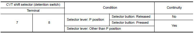
Is the inspection result normal?
YES >> Inspection End.
NO >> Replace CVT shift selector. Refer to TM "Removal and Installation".
 B2602 Shift position
Other materials:
P0711 Transmission fluid temperature
sensor A
DTC Logic
DTC DETECTION LOGIC
DTC
Trouble diagnosis name
DTC detection condition
Possible causes
P0711
Transmission Fluid Temperature
Sensor A Circuit Range/
Performance
Under the following diagnosis conditions, CVT
fluid temperature does not rise to 10C (5 ...
Precautions
Precaution for Supplemental Restraint System
(SRS) "AIR BAG" and "SEAT BELT PRE-TENSIONER"
The Supplemental Restraint System such as "AIR BAG" and "SEAT BELT PRE-TENSIONER",
used along
with a front seat belt, helps to reduce the risk or severity of injury to the
driver and ...
Categories
- Manuals Home
- Nissan Versa Owners Manual
- Nissan Versa Service Manual
- Video Guides
- Questions & Answers
- External Resources
- Latest Updates
- Most Popular
- Sitemap
- Search the site
- Privacy Policy
- Contact Us

0.0058