Nissan Versa (N17): BCM (Body control module)
Removal and Installation
CAUTION: Before replacing BCM, perform "READ CONFIGURATION" to save or print current vehicle specification.
Refer to BCS "ADDITIONAL SERVICE WHEN REPLACING CONTROL UNIT (BCM) : Description".
REMOVAL
1. Disconnect the negative battery terminal. Refer to PG "Removal and Installation".
2. Remove instrument lower panel LH. Refer to IP "Removal and Installation".
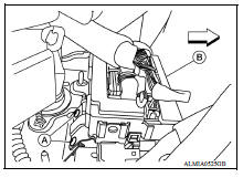
3. Remove BCM screws (A) and pull out the BCM (B).
4. Disconnect the harness connectors from the BCM (B) and remove.
 Front
Front
INSTALLATION
Installation is in the reverse order of removal.
CAUTION:
- Be sure to perform "WRITE CONFIGURATION" when replacing BCM. Refer to BCS "CONFIGURATION (BCM) : Work Procedure".
- For Canada, be sure to perform the system initialization (NATS) when replacing BCM. Refer to BCS "CONFIGURATION (BCM) : Work Procedure".
- When replacing BCM, if new BCM does not come with keyfobs attached, all existing keyfobs must be re-registered.
 Combination switch output circuit
Diagnosis Procedure Regarding Wiring Diagram information, refer to BCS "Wiring Diagram". 1.CHECK OUTPUT 1 - 5 CIRCUIT FOR OPEN 1. Turn ignition switch OFF. 2. Disconnect BCM and combinat ...
Combination switch
Exploded View 1. Combination switch 2. Combination switch harness connector Front Removal and Installation 1. Remove the steering wheel. Refer to ST "Removal and Installation". 2. Re ...
Other materials:
Event Data Recorders (EDR)
This vehicle is equipped with an Event Data Recorder
(EDR). The main purpose of an EDR is to
record, in certain crash or near crash-like situations,
such as an air bag deployment or hitting a
road obstacle, data that will assist in understanding
how a vehicle's systems performed. The EDR
is de ...
ABS Warning lamp
Component Function Check
1.CHECK ABS WARNING LAMP FUNCTION
Check that ABS warning lamp in combination meter turns ON for approximately 2
seconds after ignition switch
is turned ON.
Is the inspection result normal?
YES >> Inspection End.
NO >> Proceed to diagnosis procedure. Ref ...
Categories
- Manuals Home
- Nissan Versa Owners Manual
- Nissan Versa Service Manual
- Video Guides
- Questions & Answers
- External Resources
- Latest Updates
- Most Popular
- Sitemap
- Search the site
- Privacy Policy
- Contact Us

0.0068