Nissan Versa (N17): Combination switch output circuit
Diagnosis Procedure
Regarding Wiring Diagram information, refer to BCS "Wiring Diagram".
1.CHECK OUTPUT 1 - 5 CIRCUIT FOR OPEN
1. Turn ignition switch OFF.
2. Disconnect BCM and combination switch connectors.
3. Check continuity between BCM connector and combination switch connector.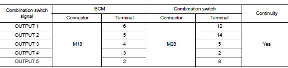
Is the inspection result normal?
YES >> GO TO 2.
NO >> Repair harness or connectors.
2.CHECK OUTPUT 1 - 5 CIRCUIT FOR SHORT
Check for continuity between BCM connector and ground.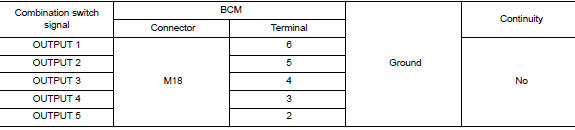
Is the inspection result normal?
YES >> Repair harness or connectors.
NO >> GO TO 3.
3.CHECK BCM INPUT SIGNAL
1. Connect BCM and combination switch connectors.
2. Turn ON any switch in the system that is malfunctioning.
3. Check voltage between BCM connector and ground.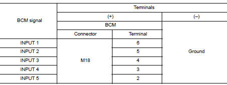
Is the inspection result normal?
Yes >> Replace BCM. Refer to BCS "Removal and Installation".
No >> Replace combination switch.
SYMPTOM DIAGNOSIS
COMBINATION SWITCH SYSTEM SYMPTOMS
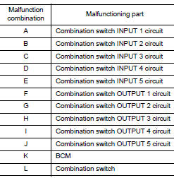
Symptom Table
1. Perform the data monitor of CONSULT to check for any malfunctioning item.
2. Check the malfunction combinations.
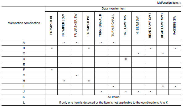
3. Identify the malfunctioning part from the agreed combination and repair or replace the part.
REMOVAL AND INSTALLATION
 Combination switch input circuit
Diagnosis Procedure Regarding Wiring Diagram information, refer to BCS "Wiring Diagram". 1.CHECK INPUT 1 - 5 CIRCUIT FOR OPEN 1. Turn ignition switch OFF. 2. Disconnect BCM and combina ...
BCM (Body control module)
Removal and Installation CAUTION: Before replacing BCM, perform "READ CONFIGURATION" to save or print current vehicle specification. Refer to BCS "ADDITIONAL SERVICE WHEN REPLACING CONTR ...
Other materials:
Installing front license plate
Use the following steps to mount the front license
plate:
Before mounting the license plate, confirm that
the following parts are enclosed in the plastic
bag:
License plate bracket
License plate bracket screws x 2
Screw grommets x 2
1. Hold the license plate bracket 1 and make
a ...
Rear oil seal
REAR OIL SEAL : Removal and Installation
REMOVAL
Remove transaxle assembly.
Remove clutch cover and clutch disk (M/T models).
Remove flywheel (M/T models) or drive plate (A/T or CVT models).
Remove rear oil seal with a suitable tool.
CAUTION:
Be careful not to damage crankshaft an ...
Categories
- Manuals Home
- Nissan Versa Owners Manual
- Nissan Versa Service Manual
- Video Guides
- Questions & Answers
- External Resources
- Latest Updates
- Most Popular
- Sitemap
- Search the site
- Privacy Policy
- Contact Us

0.0268