Nissan Versa (N17): Combination switch input circuit
Diagnosis Procedure
Regarding Wiring Diagram information, refer to BCS "Wiring Diagram".
1.CHECK INPUT 1 - 5 CIRCUIT FOR OPEN
1. Turn ignition switch OFF.
2. Disconnect BCM and combination switch connectors.
3. Check continuity between BCM connector and combination switch connector.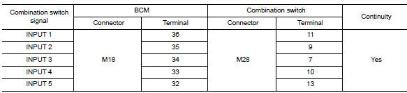
Is the inspection result normal?
YES >> GO TO 2.
NO >> Repair harness or connectors.
2.CHECK INPUT 1 - 5 CIRCUIT FOR SHORT
Check for continuity between BCM connector and ground. 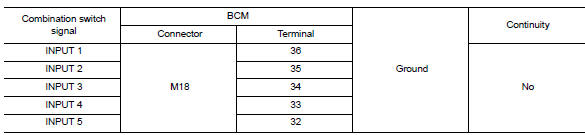
Is the inspection result normal?
YES >> Repair harness or connectors.
NO >> GO TO 3.
3.CHECK BCM OUTPUT VOLTAGE
1. Connect BCM connector.
2. Check voltage between BCM connector and ground.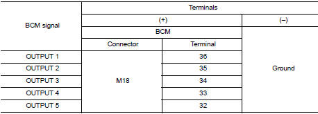
Is the inspection result normal?
YES >> Replace combination switch.
NO >> Replace BCM. Refer to BCS "Removal and Installation".
 Power supply and ground circuit
Diagnosis Procedure Regarding Wiring Diagram information, refer to BCS "Wiring Diagram". 1.CHECK FUSES AND FUSIBLE LINK Check that the following fuses and fusible link are not blown. ...
Combination switch output circuit
Diagnosis Procedure Regarding Wiring Diagram information, refer to BCS "Wiring Diagram". 1.CHECK OUTPUT 1 - 5 CIRCUIT FOR OPEN 1. Turn ignition switch OFF. 2. Disconnect BCM and combinat ...
Other materials:
Before starting the engine
Make sure the area around the vehicle is
clear.
Check fluid levels such as engine oil, coolant,
brake and clutch fluid (if so equipped),
and windshield-washer fluid as frequently as
possible, or at least whenever you refuel.
Check that all windows and lights are clean.
Visually insp ...
Continuously Variable Transmission (CVT) fluid (if so equipped)
CAUTION
NISSAN recommends using Genuine
NISSAN CVT Fluid NS-3 (or equivalent)
ONLY in NISSAN CVTs. Do not mix with
other fluids.
Do not use Automatic transmission
fluid (ATF) or Manual transmission fluid
in a NISSAN CVT, as it may damage the
CVT. Damage caused by the use of fluids
...
Categories
- Manuals Home
- Nissan Versa Owners Manual
- Nissan Versa Service Manual
- Video Guides
- Questions & Answers
- External Resources
- Latest Updates
- Most Popular
- Sitemap
- Search the site
- Privacy Policy
- Contact Us

0.0049