Nissan Versa (N17): Power supply and ground circuit
Diagnosis Procedure
Regarding Wiring Diagram information, refer to BCS "Wiring Diagram".
1.CHECK FUSES AND FUSIBLE LINK
Check that the following fuses and fusible link are not blown. 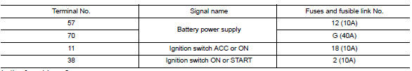
Is the fuse blown?
YES >> Replace the blown fuse or fusible link after repairing the affected circuit.
NO >> GO TO 2.
2.CHECK POWER SUPPLY CIRCUIT
1. Turn ignition switch OFF.
2. Disconnect BCM connectors.
3. Check voltage between BCM connector and ground.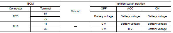
Is the inspection result normal?
YES >> GO TO 3.
NO >> Repair harness or connector.
3.CHECK GROUND CIRCUIT
Check continuity between BCM connector and ground.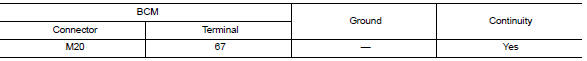
Is the inspection result normal?
YES >> Inspection End.
NO >> Repair harness or connector.
 U1010 Control unit (CAN)
DTC Logic DTC DETECTION LOGIC Diagnosis Procedure 1.REPLACE BCM When DTC "U1010 ...
Combination switch input circuit
Diagnosis Procedure Regarding Wiring Diagram information, refer to BCS "Wiring Diagram". 1.CHECK INPUT 1 - 5 CIRCUIT FOR OPEN 1. Turn ignition switch OFF. 2. Disconnect BCM and combina ...
Other materials:
Starting the engine (models without NISSAN Intelligent Key system)
1. Apply the parking brake.
2. Automatic Transmission / CVT models:
Move the shift lever to P (Park) or N (Neutral).
P (Park) is recommended.
The shift lever cannot be moved out of
P (Park) and into any of the other gear
positions if the ignition key is turned to
the OFF position or if ...
Cold weather driving
Freeing a frozen door lock
To prevent a door lock from freezing, apply deicer
through the key hole. If the lock becomes
frozen, heat the key before inserting it into the key
hole, or use the remote keyless entry key fob or
the NISSAN Intelligent Key.
Antifreeze
In the winter when it is antic ...
Categories
- Manuals Home
- Nissan Versa Owners Manual
- Nissan Versa Service Manual
- Video Guides
- Questions & Answers
- External Resources
- Latest Updates
- Most Popular
- Sitemap
- Search the site
- Privacy Policy
- Contact Us

0.0061