Nissan Versa (N17): U1010 Control unit (CAN)
DTC Logic
DTC DETECTION LOGIC 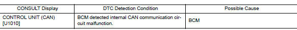
Diagnosis Procedure
1.REPLACE BCM
When DTC "U1010" is detected, replace BCM.
>> Replace BCM. Refer to BCS "Removal and Installation".
 U1000 CAN Comm
Description Refer to LAN "CAN COMMUNICATION SYSTEM : System Description". DTC Logic DTC DETECTION LOGIC NOTE: U1000 can be set if a module harness was disconnected and reconnected, ...
Power supply and ground circuit
Diagnosis Procedure Regarding Wiring Diagram information, refer to BCS "Wiring Diagram". 1.CHECK FUSES AND FUSIBLE LINK Check that the following fuses and fusible link are not blown. ...
Other materials:
Push starting
CAUTION
Do not push start this vehicle. The
three-way catalyst may be damaged
Continuously Variable Transmission
(CVT) and Manual Transmission models
cannot be push-started or tow-started.
Attempting to do so may cause transmission
damage.
For manual transmission models, never
...
Maintenance under severe operating conditions
The maintenance intervals shown on the preceding pages are for normal
operating conditions. If the vehicle is mainly operated under severe driving
conditions as shown below, more frequent maintenance must be performed on the
following items as shown in the table.
Severe driving conditions
...
Categories
- Manuals Home
- Nissan Versa Owners Manual
- Nissan Versa Service Manual
- Video Guides
- Questions & Answers
- External Resources
- Latest Updates
- Most Popular
- Sitemap
- Search the site
- Privacy Policy
- Contact Us

0.0047