Nissan Versa (N17): Exhaust manifold
Exploded View
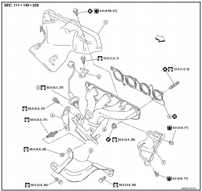
1. Exhaust manifold cover 2. Harness bracket 3. Airfuel ratio sensor 1 4. Exhaust manifold stay 5. Heat insulator 6. Exhaust manifold 7. Exhaust manifold cover 8. Gasket
 : Engine front
Removal and Installation
REMOVAL
- Remove air duct (inlet), air duct and air cleaner assembly.
- Remove exhaust center tube and front tube.
- Remove the airfuel ratio sensor harness bracket from the cylinder head on the right rear side.
- Remove exhaust manifold cover.
- Disconnect the harness from airfuel ratio sensor 1.
- Remove exhaust manifold side bolt of exhaust manifold stay.
- Remove exhaust manifold.
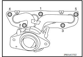
- Loosen nuts in reverse order as shown.
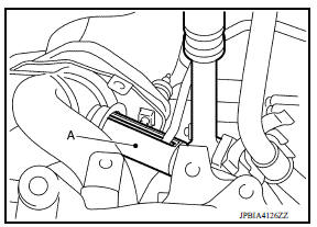
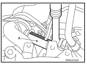
- Use Tool (A) to remove the airfuel ratio sensor 1 (if necessary).
Tool number : KV10117100 ( - )
CAUTION:
- Handle the airfuel ratio sensor carefully and avoid impacts.
- Before installing a new airfuel ratio sensor 1, clean the exhaust tube threads using suitable tool and approved antiseize lubricant.
- If airfuel ratio sensor is dropped onto a hard surface, such as a concrete floor, from a height of 0.5 m or more, discard the sensor and use a new one.
Oxygen sensor thread cleaner : - (J4389712)
Oxygen sensor thread cleaner : - (J4389718)
- Remove exhaust manifold gasket and discard.
- Remove stud bolt using suitable tool from cylinder head (if necessary)
INSPECTION AFTER REMOVAL
Mounting Surface Distortion
-
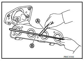
Using suitable tools (A) and (B), check the surface distortion of the exhaust manifold mating surface as shown.
-
Replace exhaust manifold if it exceeds the limit.
INSTALLATION
Installation is in the reverse order of removal. Note the following:
Exhaust manifold
1. Tighten nuts in numerical order as shown.
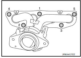
2. Tighten nuts in numerical order to the specified torque again.
Airfuel ratio sensor 1
- Use Tool (A) to install the airfuel ratio sensor 1 (if removed).
Tool number : KV10117100 ( - )
CAUTION:
- Handle it carefully and avoid impacts.
- Before installing a new airfuel ratio sensor 1, clean the exhaust tube threads using suitable tool and approved antiseize lubricant.
- Do not overtighten the airfuel ratio sensor 1. Doing so may damage the airfuel ratio sensor 1, resulting in the MIL coming on.
Oxygen sensor thread cleaner : - (J4389712)
Oxygen sensor thread cleaner : - (J4389718)
INSPECTION AFTER INSTALLATION
Inspection
- Start engine and raise engine speed to check for exhaust leaks.
 Intake manifold
Exploded View 1. EVAP canister purge volume control solenoid valve 2. Hose clamp 3. Vacuum hose 4. PCV hose 5. Hose clamp 6. Intake manifold support 7. Gasket 8. Intake manifold 9. Electric ...
Oil pan (lower)
Exploded View 1. Rear oil seal 2. Oring 3. Oil pan (upper) 4. Oil pump chain tensioner (for oil pump drive chain) 5. Oil pump drive chain 6. Crankshaft key 7. Crankshaft sprocket 8. Oil pump ...
Other materials:
Shift lock system
Component Function Check
1.CHECK SHIFT LOCK OPERATION (BRAKE PEDAL RELEASED)
Ignition switch ON.
Attempt to shift selector lever to any position other than "P" position
with brake pedal released.
Can the selector lever be shifted?
YES >> Go to TM "Diagnosis Procedure".
...
Tire pressure monitoring system
TIRE PRESSURE MONITORING SYSTEM : System Diagram
TIRE PRESSURE MONITORING SYSTEM : System
Description
The BCM has pressure judgment and trouble diagnosis functions. When the
BCM detects low inflation pressure
or another unusual symptom, the low tire pressure warning lamp in the
c ...
Categories
- Manuals Home
- Nissan Versa Owners Manual
- Nissan Versa Service Manual
- Video Guides
- Questions & Answers
- External Resources
- Latest Updates
- Most Popular
- Sitemap
- Search the site
- Privacy Policy
- Contact Us

0.0079