Nissan Versa (N17): Ignition coil, spark plug and rocker cover
Exploded View
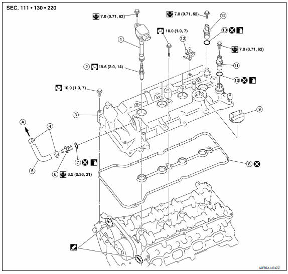
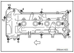
1. Ignition coil 2. Spark plug 3. Rocker cover 4. Hose cramp 5. PCV hose 6. PCV valve 7. Oring 8. Gasket 9. Oil filler cap 10. Oring 11. Intake camshaft position sensor 12. Exhaust camshaft position sensor 13. Clip A. To intake manifold
Removal and Installation
REMOVAL
- Disconnect the battery negative terminal.
- Remove intake manifold.
- Remove ignition coil.
CAUTION:
- Do not drop or shock ignition coil.
- Do not disassemble ignition coil.
- Remove fuel tube protector.
- Remove PCV hose from rocker cover.
- Remove PCV valve, if necessary.
- Remove rocker cover.
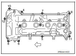
- Loosen bolts in reverse order as shown.
 : Engine front
- Remove rocker cover gasket from rocker cover.
- Use scraper to remove all traces of liquid gasket from cylinder head and front cover.
CAUTION:
Do not scratch or damage the mating surface when cleaning off old liquid gasket.
INSTALLATION
CAUTION:
Do not reuse Oring.
1. Install the rocker cover:
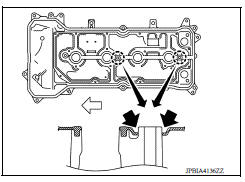
a. Press gasket onto the bosses for the rocker cover bolt holes as shown to prevent the gasket from dropping off.
: Engine front
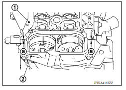
b. Apply liquid gasket to the cylinder head (1) and front cover (2) as shown.
(a) : 2.5 3.5 mm diameter
Use Genuine RTV Silicone Sealant or equivalent.
CAUTION:
- The components must be installed within 5 minutes of the liquid gasket application.
- Then allow 30 minutes for the liquid gasket to set before putting oil in the engine.
c. Install rocker cover to cylinder head.
CAUTION:
Check that the gasket has not slipped out of position.
- Tighten bolts in numerical order in two separate stages as shown.
: Engine front
2. Installation of the remaining components is in the reverse order of removal.
 Fuel injector and fuel tube
Exploded View 1. Stud bolt 2. Oring (green) 3. Fuel injector (front) 4. Clip 5. Fuel injector (rear) 6. Oring (black) 7. Fuel tube protector 8. Fuel tube 9. Clamp 10. Quick connector cap (eng ...
Timing chain
Exploded View 1. Timing chain slack guide 2. Timing chain tensioner 3. Camshaft sprocket (EXH) 4. Camshaft sprocket (INT) 5. Plug 6. Front oil seal 7. Crankshaft pulley 8. Crankshaft pulley b ...
Other materials:
Front drive shaft
Exploded View
1. Circlip 2. Dust shield 3. Slide joint housing
4. Snap ring 5. Spider assembly 6. Boot band
7. Boot 8. Shaft 9. Damper band
10. Dynamic damper 11. Circlip 12. Joint sub-assembly
Wheel side
Disassembly and Assembly
DISASSEMBLY
Transaxle Side
Fix shaft with a vise.
...
Diagnosis and repair work flow
Work Flow
OVERALL SEQUENCE
*1 SRC "Diagnosis Description" *2 SRC "SRS Operation Check" *3 SRC
"Trouble Diagnosis with
CONSULT" *4 SRC "Trouble Diagnosis without CONSULT"
DETAILED WORK FLOW
1.CUSTOMER INFORMATION
Get detailed information from the c ...
Categories
- Manuals Home
- Nissan Versa Owners Manual
- Nissan Versa Service Manual
- Video Guides
- Questions & Answers
- External Resources
- Latest Updates
- Most Popular
- Sitemap
- Search the site
- Privacy Policy
- Contact Us

0.0071