Nissan Versa (N17): Transverse link
Exploded View
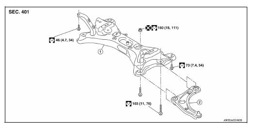
1. Front suspension member 2. Transverse link
Removal and Installation
REMOVAL
- Remove the wheel and tire assembly using power tool. Refer to WT "Adjustment".
- Remove transverse link from steering knuckle. Refer to FAX "Exploded View".
- Remove transverse link from suspension member.
INSPECTION AFTER REMOVAL
Visual Inspection
Check the following:
- Transverse link and bushing for deformation, cracks or damage. Replace it if necessary.
- Ball joint boot for cracks or other damage, and also for grease leakage. Replace it if necessary.
Ball Joint Inspection
Manually move ball stud to confirm it moves smoothly with no binding.
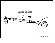
Swing Torque Inspection
NOTE: Before measurement, move ball stud at least ten times by hand to check for smooth movement.
- Hook Tool at the cutout on ball stud. Confirm Tool measurement value is within specifications when ball stud begins moving.
Tool number : - (J-44372)
Swing torque : Refer to FSU "Ball Joint".
Spring balance measurement : Refer to FSU "Ball Joint".
- If it is outside the specified range, replace transverse link assembly.
Axial End Play Inspection
- Move tip of ball stud in axial direction to check for looseness.
Axial end play : Refer to FSU "Ball Joint".
- If it is outside the specified range, replace transverse link assembly.
INSTALLATION
Installation is in the reverse order of removal.
- For tightening specifications, refer to FSU "Exploded View".
- Perform final tightening of bolts and at the front suspension member installation position (rubber bushing) under unladen conditions with tires on level ground. Check wheel alignment. Refer to FSU "Wheel Alignment".
 Front coil spring and strut
Exploded View 1. Strut assembly 2. Coil spring 3. Bound bumper 4. Spring upper seat 5. Strut mounting bearing 6. Piston rod lock nut 7. Strut mounting insulator 8. Stopper insulator 9. Stoppe ...
Front stabilizer
Exploded View 1. Stabilizer bar 2. Stabilizer clamp 3. Stabilizer bushing 4. Stabilizer connecting rod 5. Strut assembly 6. Front suspension member Front Removal and Installation REMOVAL ...
Other materials:
Child safety
WARNING
Do not allow children to play with the seat
belts. Most seating positions are
equipped with Automatic Locking Retractor
(ALR) mode seat belts. If the seat belt
becomes wrapped around a child's neck
with the ALR mode activated, the child can
be seriously injured or killed if the seat
...
Precautions
Precaution for Supplemental Restraint System
(SRS) "AIR BAG" and "SEAT BELT PRE-TENSIONER"
The Supplemental Restraint System such as "AIR BAG" and "SEAT BELT
PRE-TENSIONER", used along
with a front seat belt, helps to reduce the risk or severity of injury to the
driver and ...
Categories
- Manuals Home
- Nissan Versa Owners Manual
- Nissan Versa Service Manual
- Video Guides
- Questions & Answers
- External Resources
- Latest Updates
- Most Popular
- Sitemap
- Search the site
- Privacy Policy
- Contact Us

0.0053