Nissan Versa (N17): Front stabilizer
Exploded View
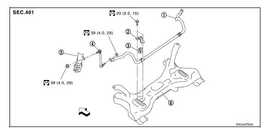
1. Stabilizer bar 2. Stabilizer clamp 3. Stabilizer bushing
4. Stabilizer connecting rod 5. Strut assembly 6. Front suspension member
 Front
Front
Removal and Installation
REMOVAL
- Remove wheel and tire assemblies using power tool. Refer to WT "Adjustment".
- Remove stabilizer connecting rod.
- Remove the pinch bolt and separate the intermediate shaft from the lower joint. Refer to ST "Removal and Installation".
- Remove the engine rear torque rod.
- Position a suitable jack under front suspension member.
CAUTION: Do not damage the front suspension member with jack.
- Remove front suspension member bolts. Refer to FSU "Removal and Installation".
- Gradually lower jack front suspension member in order to remove stabilizer bolts.
- Remove the stabilizer clamp bolts, stabilizer clamps and stabilizer bushings from front suspension member.
- Remove stabilizer bar.
INSPECTION AFTER REMOVAL
Check stabilizer bar, stabilizer connecting rod, stabilizer bushing, and stabilizer clamp for deformation, cracks, and damage. Replace it if necessary.
INSTALLATION
Installation is in the reverse order of removal.
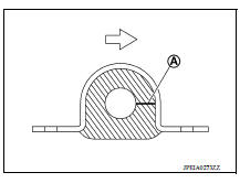
- Install the stabilizer bushing with the slit (A) facing the rear of the vehicle.
 : Rear
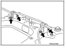
- To install stabilizer clamp bolt, temporarily tighten them in numerical order as shown and tighten them to the specified torque.
 : Front
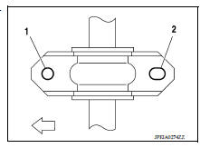
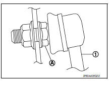
- Install the stabilizer connecting rod (1) by tightening the nut with the hexagonal part (A) on the stabilizer connecting rod side.
- Perform final tightening of bolts and nuts with the vehicle under unladen conditions with tires on level ground.
- Perform inspection after installation. Refer to FSU "Inspection and Adjustment".
 Transverse link
Exploded View 1. Front suspension member 2. Transverse link Removal and Installation REMOVAL Remove the wheel and tire assembly using power tool. Refer to WT "Adjustment". ...
Front suspension member
Exploded View 1. Front suspension member 2. Transverse link Removal and Installation REMOVAL Remove the wheel and tire assemblies using power tool. Refer to WT "Adjustment". ...
Other materials:
Trunk lid
WARNING
Do not drive with the trunk lid open. This
could allow dangerous exhaust gases
to be drawn into the vehicle. For additional
information, refer to "Exhaust
gas (carbon monoxide)" in the "Starting
and driving" section of this manual.
Closely supervise children when they
are a ...
Installing front license plate
Use the following steps to mount the front license
plate:
Before mounting the license plate, confirm that
the following parts are enclosed in the plastic
bag:
License plate bracket
License plate bracket screws x 2
Screw grommets x 2
1. Hold the license plate bracket 1 and make
a ...
Categories
- Manuals Home
- Nissan Versa Owners Manual
- Nissan Versa Service Manual
- Video Guides
- Questions & Answers
- External Resources
- Latest Updates
- Most Popular
- Sitemap
- Search the site
- Privacy Policy
- Contact Us

0.0056