Nissan Versa (N17): Fuel injector and fuel tube
Exploded View
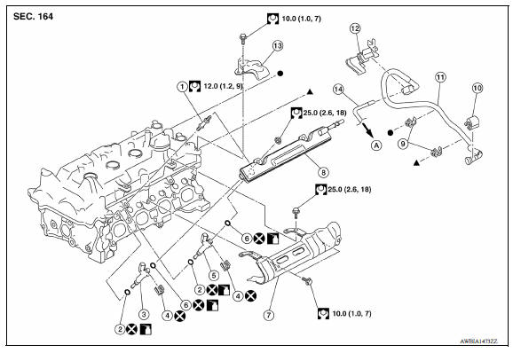
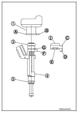
1. Stud bolt 2. Oring (green) 3. Fuel injector (front) 4. Clip 5. Fuel injector (rear) 6. Oring (black) 7. Fuel tube protector 8. Fuel tube 9. Clamp 10. Quick connector cap (engine side) 11. Fuel feed hose 12. Quick connector cap (floor pipingside) 13. Fuel connector protector 14. Fuel pipe A. To centralized underfloor piping
CAUTION:
Do not remove or disassemble parts unless instructed.
Removal and Installation
WARNING:
- Put a "CAUTION: FLAMMABLE" sign in the workshop.
- Be sure to work in a wellventilated area and furnish workshop with a CO2 fire extinguisher.
- Do not smoke while servicing fuel system. Keep open flames and sparks away from the work area.
REMOVAL
- Release the fuel pressure.
- Remove intake manifold.
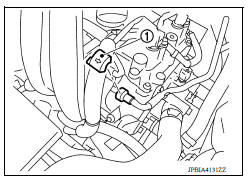
- Disconnect fuel feed hose from fuel tube. Disconnect quick connector:
(1) : Quick connector cap (engine side)
NOTE:
There is no fuel return path.
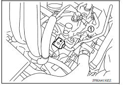
a. Remove quick connector cap (engine side) (1) from quick connector connection.
b. Disconnect fuel feed hose from hose clamp.
c. With the sleeve (B) side of quick connector release (A) facing quick connector (2), install quick connector release (A) onto fuel tube (1) as shown.
d. Insert quick connector release (A) into quick connector (2) until sleeve (B) contacts and goes no further. Hold quick connector release (A) in that position (D).
CAUTION:
Inserting quick connector release hard will not disconnect quick connector. Hold quick connector release where it contacts and goes no further.
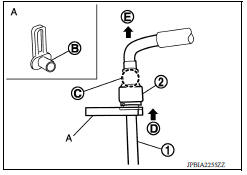
e. Draw and pull out quick connector (E) straight up from fuel tube (1).
CAUTION:
- Pull quick connector up (E) from holding position (C) as shown.
- Do not pull with lateral force applied. Oring inside quick connector may be damaged.
- Prepare container and cloth beforehand as fuel will leak out.
- Do not reuse Oring.
- Avoid fire and sparks.
- Keep parts away from heat source. Be especially careful when welding is performed.
- Do not expose parts to battery electrolyte or other acids.
- Do not bend or twist connection between quick connector and fuel feed tube during installation or removal.
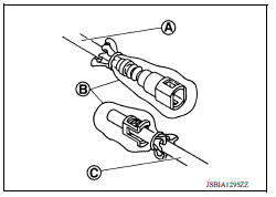
- Be sure to cover openings of disconnected fuel feed hose (A) and fuel tube (C) with plug or plastic bag (B) to avoid fuel leaks and entry of foreign material.
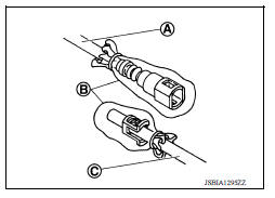
- Disconnect fuel feed hose from fuel pipe as follows:
NOTE:
There is no fuel return path.
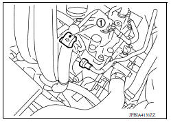
a. Remove quick connector cap (floor piping side) (1) from quick connector connection.
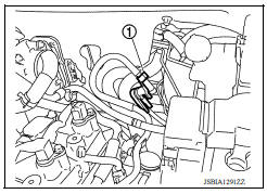
b. Disconnect fuel feed hose from hose clamp (1).
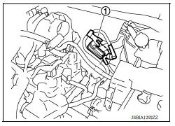
c. Hold the quick connector (1) while pushing in tabs (F), and pull out the hard tube (A).
(2) : Retainer
(B) : Connection (crosssection)
(C) : Resin tube
(D) : To under floor fuel line
(E) : To fuel tank
(G) : Disconnection
CAUTION:
- Inserting quick connector release hard will not disconnect quick connector. Hold quick connector release where it contacts and goes no further.
- The tube can be removed when the tabs are completely depressed. Do not twist it more than necessary.
- Do not use any tools to remove the quick connector.
- Keep the resin tube away from heat. Be especially careful when welding near the tube.
- Prevent acid such as battery electrolyte etc. from getting on the resin tube.
- Do not bend or twist the tube during installation and removal.
- Remove the remaining retainer only when the tube is replaced.
- When the tube is replaced, also replace the retainer.
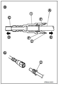
- Be sure to cover openings of disconnected pipes with plug or plastic bag (B) to avoid fuel leaks and entry of foreign material.
(A) :Fuel feed hose
(C) :Fuel tube
- Disconnect harness connector from fuel injector.
- Remove fuel tube protector.
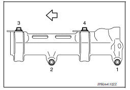
- Loosen bolts in reverse order as shown.
 : Engine front
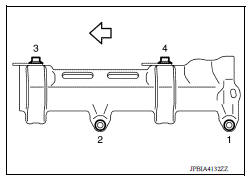
- Remove fuel injector and fuel tube assembly:
: Engine front
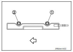
a. Loosen two nuts in reverse order as shown.
b. Pull the fuel tube straight out until injector lower Orings are clear.
c. Remove the nuts and the fuel tube.
CAUTION:
- When removing, be careful to avoid interference with fuel injectors.
- Use a shop cloth to absorb any fuel leaks from fuel tube.
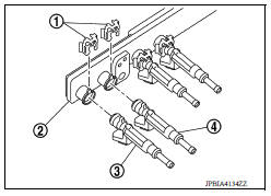
- Remove fuel injector from fuel tube:
a. Open and remove clip (1).
b. Remove fuel injectors (3) and (4) from fuel tube (2) by pulling straight out.
CAUTION:
- Be careful with remaining fuel that may leak from fuel tube.
- Be careful not to damage fuel injector nozzle during removal.
- Do not bump or drop fuel injector.
- Do not disassemble fuel injector.
- Do not reuse Orings.
INSTALLATION
CAUTION:
Do not reuse Orings.
1. Note the following, and install new Orings on the fuel injector.
CAUTION:
- Upper and lower Orings are different. Be careful not to interchange them.
Fuel tube side : Black Nozzle side : Green
- Handle Oring with bare hands. Do not wear gloves.
- Lubricate Oring with new engine oil.
- Do not clean Oring with solvent.
- Check that Oring and its mating part are free of foreign material.
- When installing Oring, be careful not to scratch it.
- Do not twist or stretch Oring. If Oring was stretched while it was being attached, allow it to retract before inserting it into fuel tube.
- Insert Oring straight into fuel tube. Do not angle or twist it.
2. Install fuel injector (4) to fuel tube (1):
a. Insert new clip (2) into clip groove (G) on fuel injector (4).
- Insert new clip (2) so that protrusion (F) of fuel injector matches cutout (D) of clip.
(3) : Oring (black) (5) : Oring (green)
CAUTION:
- Do not reuse clip. Replace it with a new one.
- Be careful to keep clip from interfering with Oring. If interference occurs, replace Oring.
b. Insert fuel injector (4) into fuel tube (1) with clip (2) attached.
- Insert fuel injector (4) while matching it to the axial center.
- Insert fuel injector (4) so that protrusion (B) of fuel tube matches cutout (C) of clip (2).
- Check that fuel tube flange (A) is securely located in flange groove (E) on clip (2).
c. Check that installation is complete by checking that fuel injector (4) does not rotate or come off.
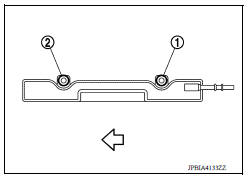
3. Set fuel tube and fuel injector assembly in position for installation on cylinder head.
CAUTION:
For installation, be careful not to interfere with fuel injector nozzle.
-
Tighten bolts in numerical order as shown.
 : Engine front
4. Install fuel tube protector.
-
Tighten bolts in numerical order as shown.
: Engine front
5. Connect harness connector to fuel injector.
6. Connect fuel feed tube (engine side):
a. Check for damage or foreign material on the fuel tube and quick connector.
b. Apply new engine oil lightly to area around the top of fuel tube.
c. Align center to insert quick connector straight into fuel tube.
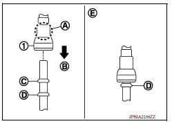
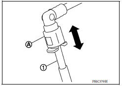
-
Insert quick connector (1) to fuel tube until the top spool (C) on fuel tube is inserted completely and the 2nd level spool (D) is positioned slightly below quick connector bottom end.
(B) : Upright insertion
(E) : Correctly connected
CAUTION:
-
Hold in position (A) as shown when inserting fuel tube into quick connector.
-
Carefully align center to avoid inclined insertion to prevent damage to Oring inside quick connector.
-
Insert until you hear a "click" sound and actually feel the engagement.
d. To avoid misidentification of engagement with a similar sound, pull quick connector hard by hand. Check it is completely engaged (connected) so that it does not come out from fuel tube.
e. Install quick connector cap (engine side) (1) to quick connector connection.
-
Install quick connector cap (engine side) (1) with the side arrow facing quick connector side (fuel feed tube side) as shown.
CAUTION:
-
Check that the quick connector and fuel tube are securely engaged with the quick connector cap (engine side) groove.
-
If the quick connector cap (engine side) cannot be installed easily the quick connector may not be connected correctly. Remove and reconnect.
f. Install fuel feed hose to hose clamp.
7. Connect fuel feed tube (floor piping side):
a. Check the connection for damage or any foreign materials.
b. Align the quick connector with the tube, then insert the connector straight into the centralized under floor piping until a click is heard.
c. After connecting, check that the connection is secure:
-
Visually confirm that the two retainer tabs are connected to the connector.
-
With the fuel feed hose not fixed to the clamp, pull quick connector (A) hard by hand to check that the quick connector (A) is not disconnected from the centralized underfloor piping (1) and that the quick connector (1) is securely connected.
8. Install remaining parts in the reverse order of removal.
INSPECTION AFTER INSTALLATION
Check on Fuel Leaks
1. Turn ignition switch ON with the engine stopped. Ensure there are no fuel leaks at fuel pipe connection points.
NOTE:
Use mirrors for checking points out of clear sight.
2. Start the engine and increase engine speed. Check again that there are no fuel leaks.
CAUTION:
Do not touch the engine immediately after stopped, as the engine becomes extremely hot.
 Oil pan (lower)
Exploded View 1. Rear oil seal 2. Oring 3. Oil pan (upper) 4. Oil pump chain tensioner (for oil pump drive chain) 5. Oil pump drive chain 6. Crankshaft key 7. Crankshaft sprocket 8. Oil pump ...
Ignition coil, spark plug and rocker cover
Exploded View 1. Ignition coil 2. Spark plug 3. Rocker cover 4. Hose cramp 5. PCV hose 6. PCV valve 7. Oring 8. Gasket 9. Oil filler cap 10. Oring 11. Intake camshaft position sensor 12. Exhau ...
Other materials:
Preparation
Special Service Tool
The actual shape of Kent-Moore tools may differ from those of special service
tools illustrated here.
HFC-134a (R-134a) Service Tool and Equipment
Do not mix HFC-134a (R-134a) refrigerant and/or its specified oil with CFC-12
(R-12) refrigerant and/or its oil.
Separ ...
Insufficient cooling
Description
Symptom
Insufficient cooling
No cool air comes out. (Air flow volume is normal.)
Diagnosis Procedure
NOTE:
Perform self-diagnosis with CONSULT before performing symptom diagnosis. If any
malfunction result or DTC
is detected, perform the corresponding diagnosis.
1.CHE ...
Categories
- Manuals Home
- Nissan Versa Owners Manual
- Nissan Versa Service Manual
- Video Guides
- Questions & Answers
- External Resources
- Latest Updates
- Most Popular
- Sitemap
- Search the site
- Privacy Policy
- Contact Us

0.0052