
Nissan Versa (N17): Condenser
Exploded View
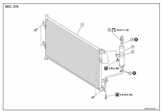
1. Condenser 2. O-rings 3. Liquid tank bracket 4. Liquid tank 5. O-ring 6. Refrigerant pressure sensor
Removal and Installation
CAUTION: Perform oil return operation before each refrigeration system disassembly. However, if a large amount of refrigerant or oil is detected do not perform oil return operation. Refer to HA "Perform Oil Return Operation".
REMOVAL
- Use refrigerant collecting equipment (for HFC-134a) to discharge the refrigerant. Refer to HA "Recycle Refrigerant".
- Remove the radiator core upper support. Refer to CO "Removal and Installation".
- Remove high-pressure flexible hose bolt and disconnect high-pressure
flexible hose from the condenser.
CAUTION: Cap or wrap the joint of the A/C piping and condenser with suitable material such as vinyl tape to avoid the entry of air.
- Remove high-pressure flexible hose bolt and disconnect high-pressure
pipe from the condenser.
CAUTION: Cap or wrap the joint of the A/C piping and condenser with suitable material such as vinyl tape to avoid the entry of air.
- Remove the condenser and liquid tank assembly.
CAUTION: Be careful not to damage core surface of condenser.
INSTALLATION
Installation is in the reverse order of removal.
CAUTION:
- Do not reuse O-rings.
- Apply A/C oil to the O-ring of the high-pressure flexible hose and high-pressure pipe for installation.
- Perform oil adjusting procedure before installing new condenser. Refer to HA "Oil Adjusting Procedure for Components Replacement Except Compressor".
- After charging A/C refrigerant, check for leaks. Refer to HA "Leak Test".
 Compressor
Exploded View 1. Compressor Removal and Installation CAUTION: Perform oil return operation before each refrigeration system disassembly. However, if a large amount of refrigerant or oil i ...
Low-pressure flexible hose
Removal and Installation CAUTION: Perform oil return operation before each refrigeration system disassembly. However, if a large amount of refrigerant or oil is detected, do not perform oil retu ...
Other materials:
P0507 ISC system
Description
The ECM controls the engine idle speed to a specified level through the fine
adjustment of the air, which is let
into the intake manifold, by operating the electric throttle control actuator.
The operating of the throttle valve is
varied to allow for optimum control of the engine ...
Shift lock system
Component Function Check
1.CHECK SHIFT LOCK OPERATION (BRAKE PEDAL RELEASED)
Ignition switch ON.
Attempt to shift selector lever to any position other than "P" position
with brake pedal released.
Can the selector lever be shifted?
YES >> Go to TM "Diagnosis Procedure".
...
Categories
- Manuals Home
- Nissan Versa Owners Manual
- Nissan Versa Service Manual
- Video Guides
- Questions & Answers
- External Resources
- Latest Updates
- Most Popular
- Sitemap
- Search the site
- Privacy Policy
- Contact Us

0.0052