Nissan Versa (N17): Intake manifold
Exploded View
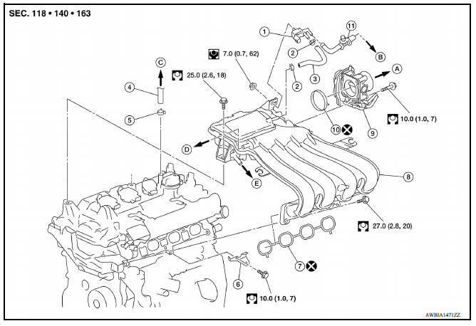
1. EVAP canister purge volume control solenoid valve 2. Hose clamp 3. Vacuum hose 4. PCV hose 5. Hose clamp 6. Intake manifold support 7. Gasket 8. Intake manifold 9. Electric throttle control actuator 10. Gasket 11. EVAP service port
A. To air duct B. To centralized underfloor piping C. To brake booster D. To air duct E. To rocker cover
Removal and Installation
REMOVAL
NOTE:
When removing components such as hoses, tubes/lines, etc., cap or plug openings to prevent fluid from spilling.
- Remove air duct (inlet), air duct and air cleaner assembly.
- Disconnect water hoses from electric throttle control actuator.
CAUTION:
- Perform this step when the engine is cold.
- Do not spill engine coolant on drive belt.
- Remove electric throttle control actuator.
CAUTION:
- Handle carefully to avoid any shock to electric throttle control actuator.
- Do not disassemble electric throttle control actuator.
- Disconnect harness connector and vacuum hose from EVAP purge control solenoid valve.
CAUTION:
Handle EVAP canister purge volume control solenoid valve carefully and avoid impacts.
- Disconnect vacuum hose for brake booster from intake manifold.
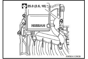
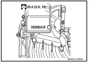
- Remove intake manifold bolts at the rocker cover.
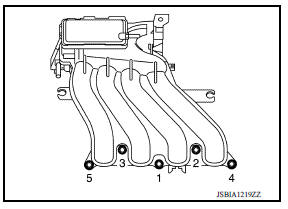
- Loosen bolts in reverse order as shown.
CAUTION:
Cover engine openings to avoid entry of foreign materials.
- Remove intake manifold.
- Remove EVAP purge control solenoid valve from intake manifold if necessary.
CAUTION:
Handle EVAP canister purge volume control solenoid valve carefully and avoid impacts.
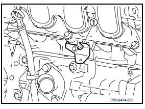
- Remove intake manifold support (1) if necessary.
CAUTION:
The intake manifold support functions as a guide for installing the intake manifold.
INSTALLATION
Installation is in the reverse order of removal.
Intake Manifold
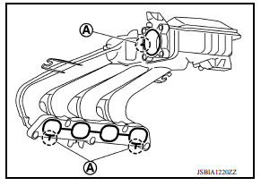
- Install the new gasket to the intake manifold.
- Align the protrusions used for checking gasket installation condition with the clearance grooves (A) of the intake manifold groove.
CAUTION:
Do not reuse the gasket.
NOTE:
New gasket for electronicallycontrolled throttle can be installed when the electronicallycontrolled throttle is installed.
- Place the intake manifold into position.
CAUTION:
Check that the oil level gauge guide is not detached from the securing clip of the water inlet due to interference of intake manifold.
- Tighten the bolts to specification in the numerical order as shown.
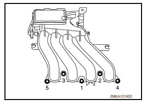
- Tighten the bolts to specification in the numerical order as shown.
Electric Throttle Control Actuator
- Tighten bolts of electric throttle control actuator equally and diagonally in several steps.
- Perform "Throttle Valve Closed Position Learning" after repair when removing harness connector of the electric throttle control actuator.
- Perform "Throttle Valve Closed Position Learning" and "Idle Air Volume Learning" after repair when replacing electric throttle control actuator.
 Air cleaner and air duct
Exploded View 1. Clamp 2. PCV hose 3. Clamp 4. Mount rubber 5. Air duct (inlet) 6. Air cleaner body 7. Grommet 8. Air cleaner filter 9. Air cleaner cover 10. Mass air flow sensor 11. Air duct ...
Exhaust manifold
Exploded View 1. Exhaust manifold cover 2. Harness bracket 3. Airfuel ratio sensor 1 4. Exhaust manifold stay 5. Heat insulator 6. Exhaust manifold 7. Exhaust manifold cover 8. Gasket : Engi ...
Other materials:
Air cleaner and air duct
Exploded View
1. Clamp 2. PCV hose 3. Clamp
4. Mount rubber 5. Air duct (inlet) 6. Air cleaner body
7. Grommet 8. Air cleaner filter 9. Air cleaner cover
10. Mass air flow sensor 11. Air duct 12. Clamp
Removal and Installation
REMOVAL
NOTE:
Mass air flow sensor is removable as an assemb ...
Intake valve timing control
Intake valve timing control : System Diagram
Intake valve timing control : system description
INPUT/OUTPUT SIGNAL CHART
Sensor
Input signal to ECM
ECM function
Actuator
Crankshaft position sensor (POS)
Engine speed*1
Piston position
Intake valve timing
con ...
Categories
- Manuals Home
- Nissan Versa Owners Manual
- Nissan Versa Service Manual
- Video Guides
- Questions & Answers
- External Resources
- Latest Updates
- Most Popular
- Sitemap
- Search the site
- Privacy Policy
- Contact Us

0.0057