Nissan Versa (N17): Air cleaner and air duct
Exploded View
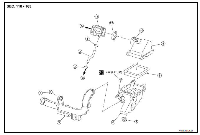
1. Clamp 2. PCV hose 3. Clamp 4. Mount rubber 5. Air duct (inlet) 6. Air cleaner body 7. Grommet 8. Air cleaner filter 9. Air cleaner cover 10. Mass air flow sensor 11. Air duct 12. Clamp
Removal and Installation
REMOVAL
NOTE:
Mass air flow sensor is removable as an assembly with the air cleaner cover.
- Remove air duct (inlet) from the air cleaner body.
- Disconnect PCV hose from the air duct.
- Remove the air duct (between air cleaner case and electric throttle control actuator).
- Add matching marks if necessary for easier installation.
- Remove air cleaner assembly with the following steps:
- Disconnect the harness connector from mass air flow sensor.
- Remove the two air cleaner body bolts.
- Pull up on the air cleaner assembly to disengage it from the grommet and remove the air cleaner assembly.
CAUTION:
- Do not shock the mass air flow sensor.
- Do not disassemble the mass air flow sensor.
- Do not touch the sensor of the mass air flow sensor.
INSPECTION AFTER REMOVAL
Inspect air duct (inlet) and air duct for cracks, tears, or breaks.
Replace air duct (inlet) and air duct if any problems are found.
INSTALLATION
Installation is in the reverse order of removal.
NOTE:
Align marks, attach each joint and screw clamps firmly.
 Drive belt idler pulley
Exploded View 1. Generator bracket 2. Center shaft 3. Spacer 4. Adjusting bolt 5. Washer 6. Idler pulley 7. Plate Removal and Installation REMOVAL Remove the fender protector (RH). Remo ...
Intake manifold
Exploded View 1. EVAP canister purge volume control solenoid valve 2. Hose clamp 3. Vacuum hose 4. PCV hose 5. Hose clamp 6. Intake manifold support 7. Gasket 8. Intake manifold 9. Electric ...
Other materials:
Windows
Power windows (if so equipped)
WARNING
Make sure that all passengers have
their hands, etc. inside the vehicle while
it is in motion and before closing the
windows. Use the window lock switch to
prevent unexpected use of the power
windows
To help avoid risk of injury or death
thr ...
Vehicle Dynamic Control (VDC) system (if so equipped)
The VDC system uses various sensors to monitor
driver inputs and vehicle motion. Under certain
driving conditions, the VDC System helps to perform
the following functions:
Controls brake pressure to reduce wheel
slip on one slipping drive wheel so power is
transferred to a non slipping drive w ...
Categories
- Manuals Home
- Nissan Versa Owners Manual
- Nissan Versa Service Manual
- Video Guides
- Questions & Answers
- External Resources
- Latest Updates
- Most Popular
- Sitemap
- Search the site
- Privacy Policy
- Contact Us

0.0051