Nissan Versa (N17): Drive belt idler pulley
Exploded View
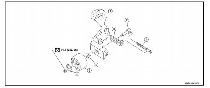
1. Generator bracket 2. Center shaft 3. Spacer 4. Adjusting bolt 5. Washer 6. Idler pulley 7. Plate
Removal and Installation
REMOVAL
- Remove the fender protector (RH).
- Remove the air duct inlet assembly.
- Remove drive belt.
- Remove the lock nut, and then remove the plate, idler pulley, and washer.
- Remove the center shaft together with the spacer and the adjusting bolt.
INSTALLATION
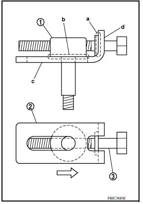
- Insert the center shaft (1) into the slide groove of the spacer (2).Fully screw in the adjusting bolt (3) in the belt loosening direction
(
 ).
).
- At that time, place the flange (a) of the adjusting bolt and the seat (b) of the center shaft on the spacer.
- Place each surface (c and d) of the spacer on the generator bracket. Install the washer, idler pulley, and plate, and then temporarily tighten the lock nut.
Lock nut (Temporary tightening) : 4.4 N*m (0.45 kgm, 39 inlb)
- Installation is in the reverse order of removal.
 Spark plug
Exploded View 1. Ignition coil 2. Spark plug Removal and Installation REMOVAL 1. Remove ignition coil. CAUTION: Do not drop or shock ignition coil. 2. Remove spark plug using a suitable tool. ...
Air cleaner and air duct
Exploded View 1. Clamp 2. PCV hose 3. Clamp 4. Mount rubber 5. Air duct (inlet) 6. Air cleaner body 7. Grommet 8. Air cleaner filter 9. Air cleaner cover 10. Mass air flow sensor 11. Air duct ...
Other materials:
Installing front license plate
Use the following steps to mount the front license
plate:
Before mounting the license plate, confirm that
the following parts are enclosed in the plastic
bag:
License plate bracket
License plate bracket screws x 2
Screw grommets x 2
1. Hold the license plate bracket 1 and make
a ...
P0744 Torque converter
Description
This DTC is detected when the torque converter clutch solenoid valve is
electrically normal but the torque converter
clutch does not engage. This is not due to an electrical malfunction (circuit
open or shorted), but is
instead due to a mechanical malfunction (sticking of the cont ...
Categories
- Manuals Home
- Nissan Versa Owners Manual
- Nissan Versa Service Manual
- Video Guides
- Questions & Answers
- External Resources
- Latest Updates
- Most Popular
- Sitemap
- Search the site
- Privacy Policy
- Contact Us

0.0047