Nissan Versa (N17): U1000 CAN Comm
Description
Refer to LAN "CAN COMMUNICATION SYSTEM : System Description".
DTC Logic
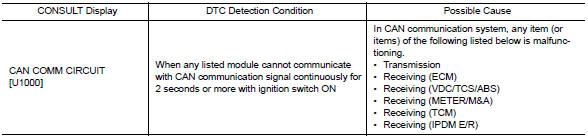
DTC DETECTION LOGIC
NOTE:
U1000 can be set if a module harness was disconnected and reconnected, perhaps
during a repair. Confirm
that there are actual CAN diagnostic symptoms and a present DTC by performing
the Self Diagnostic Result
procedure.
Diagnosis Procedure
1. PERFORM SELF DIAGNOSTIC RESULT
1. Turn ignition switch ON and wait for 2 second or more.
2. Check "SELF- DIAG RESULTS".
Is "CAN COMM CIRCUIT" displayed?
YES >> Perform CAN Diagnosis as described in DIAGNOSIS section of CONSULT Operation Manual.
NO >> Refer to GI "Intermittent Incident".
 Inspection and adjustment
U1010 Control unit (CAN)
DTC Logic DTC DETECTION LOGIC Diagnosis Procedure 1.REPLACE BCM When DTC "U1010 ...
Other materials:
Service data and specifications
(SDS)
Periodical Maintenance Specification
ENGINE OIL CAPACITY (APPROXIMATE)
...
Final drive
Exploded View
1. Differential side bearing outer race 2. Differential side bearing 3. Final
drive
: Replace the parts as a set.
Disassembly
Remove differential side bearings, using Tool (A) and suitable tool.
Tool number : ST33052000 ( - )
Assembly
Install differential sid ...
Categories
- Manuals Home
- Nissan Versa Owners Manual
- Nissan Versa Service Manual
- Video Guides
- Questions & Answers
- External Resources
- Latest Updates
- Most Popular
- Sitemap
- Search the site
- Privacy Policy
- Contact Us

0.005