Nissan Versa (N17): C1606 EPS Motor
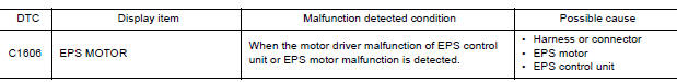
DTC Logic
DTC DETECTION LOGIC
DTC CONFIRMATION PROCEDURE
1.PRECONDITIONING
If "DTC CONFIRMATION PROCEDURE" has been previously conducted, always turn ignition switch OFF and wait at least 10 seconds before conducting the next test.
>> GO TO 2.
2.DTC REPRODUCTION PROCEDURE
With CONSULT
- Turn the ignition switch OFF to ON.
- Perform "EPS" self-diagnosis.
Is DTC "C1606" detected?
YES >> Proceed to diagnosis procedure. Refer to STC "Diagnosis Procedure".
NO >> Inspection End.
Diagnosis Procedure
1.CHECK EPS MOTOR
Check the EPS motor. Refer to STC "Component Inspection".
Is the inspection result normal?
YES >> GO TO 2.
NO >> EPS motor is malfunction. Replace steering column assembly. Refer to ST"Removal and Installation".
2.CHECK CONNECTOR
- Turn ignition switch OFF.
- Disconnect EPS motor harness connector.
- Check terminal for deformation, disconnection, looseness, and so on. If any malfunction is found, repair or replace terminal.
Is the inspection result normal?
YES >> Replace EPS control unit. Refer to STC, "Removal and Installation".
NO >> Repair or replace malfunctioning component.
Component Inspection
1.CHECK EPS MOTOR
- Turn the ignition switch OFF.
- Disconnect EPS motor harness connector.
- Check resistance between EPS motor connector terminals.
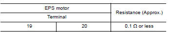
Is the inspection result normal?
YES >> Inspection End.
NO >> EPS motor is malfunctioning. Replace steering column assembly. Refer to ST "Removal and Installation".
 C1604 Torque sensor
C1607, C1608 EPS Control unit
DTC Logic DTC DETECTION LOGIC DTC CONFIRMATION PROCEDURE 1.PRECONDITIONING If "DTC CONFIRMATION PROCEDURE" has been previously conducted, always turn ...
Other materials:
Side oil seal
Removal and Installation
REMOVAL
Remove front drive shaft from transaxle assembly. Refer to FAX, "Removal
and Installation".
Remove differential side oil seal (1) using suitable tool.
CAUTION:
Do not damage transaxle case and clutch housing.
INSTALLATION
& ...
P074B Unable to engage 3GR
Description
This malfunction is detected when the A/T does not shift into 3GR position as
instructed by TCM. This is not
only caused by electrical malfunction (circuits open or shorted) but by
mechanical malfunction such as control
valve sticking, improper solenoid valve operation, etc.
DTC ...
Categories
- Manuals Home
- Nissan Versa Owners Manual
- Nissan Versa Service Manual
- Video Guides
- Questions & Answers
- External Resources
- Latest Updates
- Most Popular
- Sitemap
- Search the site
- Privacy Policy
- Contact Us

0.0061