Nissan Versa (N17): Headlamp (HI) circuit
Description
The IPDM E/R (intelligent power distribution module engine room) controls the headlamp high relay based on inputs from the BCM via the CAN communication lines. When the headlamp high relay is energized, power flows through fuses 34 and 35, located in the IPDM E/R. Power then flows to the front combination lamp LH and RH high beams.
Component Function Check
1.CHECK HEADLAMP (HI) OPERATION
WITHOUT CONSULT
- Start IPDM E/R auto active test. Refer to PCS "Diagnosis Description" (with Intelligent Key) or PCS "Diagnosis Description" (without Intelligent Key).
- Check that the headlamp switches to the high beam.
CONSULT
- Select EXTERNAL LAMPS of IPDM E/R active test item.
- While operating the test items, check that the headlamp switches to the high beam.
HI : Headlamp switches to the high beam.
OFF : Headlamp OFF
Does the headlamp switch to high beam?
YES >> Headlamp (HI) circuit is normal.
NO >> Refer to EXL "Diagnosis Procedure".
Diagnosis Procedure
Regarding Wiring Diagram information, refer to EXL "Wiring Diagram".
1.CHECK HEADLAMP (HI) FUSES
1. Turn the ignition switch OFF.
2. Check that the following fuses are not blown.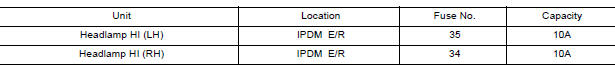
Is the fuse blown?
YES >> Replace the fuse after repairing the affected circuit.
NO >> GO TO 2.
2.CHECK HIGH BEAM BULB
Check the applicable high beam bulb to be sure the proper bulb standard is in use and the bulb is not open.
Is the bulb OK?
YES >> GO TO 3.
NO >> Replace the bulb.
3.CHECK HEADLAMP (HI) OUTPUT VOLTAGE
1. Turn the ignition switch OFF.
2. Disconnect the front combination lamp connector E25 or E26.
3. Turn the ignition switch ON.
4. Turn the high beam headlamps ON.
5. With the high beam headlamps ON, check the voltage between the combination
lamp connector and
ground.
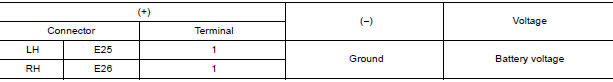
Is the inspection result normal?
YES >> GO TO 5.
NO >> GO TO 4.
4.CHECK HEADLAMP (HI) CIRCUIT FOR OPEN
1. Turn the ignition switch OFF.
2. Disconnect IPDM E/R connector E45.
3. Check continuity between the IPDM E/R harness connector E45 and the front
combination lamp harness
connector E25 or E26.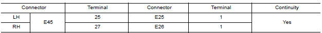
Is the inspection result normal?
YES >> Replace IPDM E/R. Refer to PCS "Removal and Installation" (with Intelligent Key) or PCS "Removal and Installation" (without Intelligent Key).
NO >> Repair or replace the harness or connector.
5.CHECK FRONT COMBINATION LAMP (HI) GROUND CIRCUIT
Check continuity between the front combination lamp harness connector and
ground.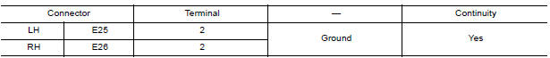
Is the inspection result normal?
YES >> Replace malfunctioning lamp.
NO >> Repair or replace the harness or connector (without daytime light system).
>> GO TO 6 (with daytime light system).
6.CHECK FRONT COMBINATION LAMP LH TO DAYTIME LIGHT RELAY 1 GROUND CIRCUIT
1. Disconnect daytime light relay 1 connector E37.
2. Check continuity between the daytime light relay 1 harness connector E37
and the front combination lamp
LH harness connector E25.
Is the inspection result normal?
YES >> GO TO 7.
NO >> Repair or replace the harness or connector.
7.CHECK DAYTIME LIGHT RELAY 1 GROUND CIRCUIT
Check continuity between the daytime light relay 1 harness connector E37 and
ground.
Is the inspection result normal?
YES >> Replace daytime light relay 1.
NO >> Repair or replace the harness or connector.
 Power supply and ground circuit
Headlamp (LO) circuit
Description The IPDM E/R (intelligent power distribution module engine room) controls the headlamp low relay based on inputs from the BCM via the CAN communication lines. When the headlamp low re ...
Other materials:
P0963 Pressure control solenoid A
DTC Logic
DTC DETECTION LOGIC
DTC
Trouble diagnosis name
DTC detection condition
Possible causes
P0963
Pressure Control Solenoid "A"
Control Circuit High
The following diagnosis conditions
are met, and the current
monitor reading of the TCM line
pressure ...
P0965 Pressure control solenoid B
DTC Logic
DTC DETECTION LOGIC
DTC
Trouble diagnosis name
DTC detection condition
Possible causes
P0965
Pressure control solenoid B
control circuit range performance
The detection conditions continuously for 5
seconds or more under the following diagnosis
con ...
Categories
- Manuals Home
- Nissan Versa Owners Manual
- Nissan Versa Service Manual
- Video Guides
- Questions & Answers
- External Resources
- Latest Updates
- Most Popular
- Sitemap
- Search the site
- Privacy Policy
- Contact Us

0.0055