Nissan Versa (N17): Battery saver output/power supply circuit
Description
Provides the battery saver output/power supply. Also cuts the power supply when the interior lamp battery saver is activated.
Component Function Check
1.CHECK BATTERY SAVER OUTPUT/POWER SUPPLY FUNCTION
CONSULT
1. Turn ignition switch ON.
2. Turn each interior lamp to the ON position.
- Interior room lamp
- Map lamp (if equipped)
- Trunk room lamp
3. Select BATTERY SAVER of BCM (BATTERY SAVER) active test item.
4. While operating the test item, check that each interior room lamp turns ON/OFF.
OFF : Interior room lamp OFF
ON : Interior room lamp ON
Is the inspection result normal?
YES >> Battery saver output/power supply circuit is normal.
NO >> Refer to INL "Diagnosis Procedure".
Diagnosis Procedure
Regarding Wiring Diagram information, refer to INL "Wiring Diagram".
1.CHECK BATTERY SAVER OUTPUT/POWER SUPPLY OUTPUT
CONSULT
1. Turn ignition switch ON.
2. Select BATTERY SAVER of BCM (BATTERY SAVER) active test item.
3. While operating the test item, check voltage between BCM connector and
ground.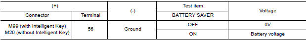
Is the inspection result normal?
YES >> GO TO 2.
NO >> Replace BCM after making sure battery saver output/power supply circuit is not shorted to voltage.
Refer to BCS "Removal and Installation" (with Intelligent Key) or BCS "Removal and Installation" (without Intelligent Key).
2.CHECK BATTERY SAVER OUTPUT/POWER SUPPLY OPEN CIRCUIT
1. Turn ignition switch OFF.
2. Disconnect the following connectors.
- BCM
- Interior room lamp
- Map lamp (if equipped)
- Trunk room lamp
3. Check continuity between BCM connector and each interior lamp connector.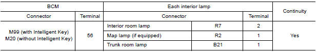
Is the inspection result normal?
YES >> GO TO 3.
NO >> Repair or replace the harness or connector.
3.CHECK BATTERY SAVER OUTPUT/POWER SUPPLY SHORT CIRCUIT
Check continuity between BCM connector and ground.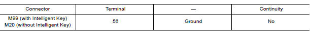
Is the inspection result normal?
YES >> Check that each interior room lamp has no internal short circuit.
NO >> Repair or replace the harness or connector.
 Power supply and ground circuit
Interior room lamp control circuit
Description Controls each interior room lamp (ground side) by PWM signal. NOTE: PWM signal control period is approximately 250 Hz (in the gradual brightening/dimming). ...
Other materials:
Doors
When the doors are locked using one of the
following methods, the doors cannot be opened
using the inside or outside door handles. The
doors must be unlocked to open the doors.
WARNING
Before opening any door, always look
for and avoid oncoming traffic.
To help avoid risk of injury or de ...
Vehicle identification
Vehicle identification number (VIN) plate
The vehicle identification number (VIN) plate is
attached as shown. This number is the identification
for your vehicle and is used in the vehicle
registration.
Vehicle identification number (chassis number)
The vehicle identification number i ...
Categories
- Manuals Home
- Nissan Versa Owners Manual
- Nissan Versa Service Manual
- Video Guides
- Questions & Answers
- External Resources
- Latest Updates
- Most Popular
- Sitemap
- Search the site
- Privacy Policy
- Contact Us

0.0054