Nissan Versa (N17): P0717 Input speed sensor A
DTC Logic
DTC DETECTION LOGIC
| DTC | Trouble diagnosis name | DTC detection condition | Possible causes |
| P0717 | Input/Turbine Speed Sensor "A" Circuit No Signal | Under the following diagnosis
conditions, the input speed sensor
value is less than 600 rpm
continuously for 5 seconds or
more. - Diagnosis condition - Engine speed: More than 1,500 rpm - Position: Other than P or N - Idle switch: OFF - Vehicle speed: More than 40 km/h (25 MPH) - TCM power supply voltage: 10 V <TCM power supply voltage <16 V |
|
DTC CONFIRMATION PROCEDURE
CAUTION: Be careful of the driving speed.
1.PREPARATION BEFORE WORK
If another "DTC CONFIRMATION PROCEDURE" occurs just before, turn ignition switch OFF and wait for at least 10 seconds, then perform the next test.
>> GO TO 2.
2.CHECK DTC DETECTION
- Start the engine.
- Drive the vehicle.
- Maintain the following conditions for 5 seconds or more.
- Stop the vehicle.
- Check the first trip DTC.
Engine speed : More than 1,500 rpm
Accelerator pedal position : 0.5/8.0 or more
Selector lever : D position
Vehicle speed : More than 40 km/h (25 MPH)
Is "P0717" detected?
YES >> Go to TM, "Diagnosis Procedure".
NO >> INSPECTION END
Diagnosis Procedure
1.CHECK INPUT SPEED SENSOR POWER CIRCUIT
- Turn ignition switch OFF.
- Disconnect the transaxle assembly connector.
- Turn ignition switch ON.
- Check the voltage between the A/T unit harness connector and ground.
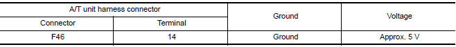
Is the check result normal?
YES >> GO TO 2.
NO >> Check the TCM power supply. Refer to TM, "Diagnosis Procedure".
2.CHECK INPUT SPEED SENSOR GROUND CIRCUIT
- Turn ignition switch OFF.
- Check the continuity between the A/T unit harness connector and ground.
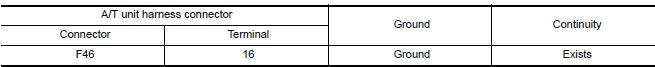
Is the check result normal?
YES >> GO TO 3.
NO >> Check or repair the malfunction items.
3.CHECK INPUT SPEED SENSOR SIGNAL CIRCUIT
- Disconnect the TCM connector.
- Check the continuity between the TCM harness connector and the A/T unit
harness connector.
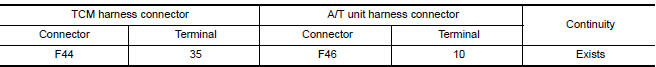
Is the check result normal?
YES >> GO TO 4.
NO >> Check or repair the malfunction items.
4.CHECK INPUT SPEED SENSOR TCM CIRCUIT (CHECK 3)
Check the continuity between TCM harness connector and ground.
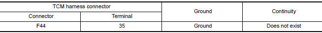
Is the check result normal?
YES >> GO TO 5.
NO >> Check or repair the malfunction items.
5.CHECK TCM INPUT SIGNALS
- Connect all of the disconnected connectors.
- Lift the vehicle.
- Start the engine.
- Check the frequency of the input speed sensor.
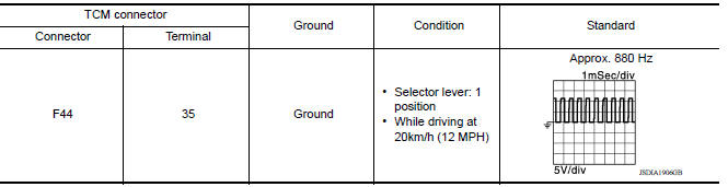
Is the check result normal?
YES >> Perform a simulation test to judge the cause of the malfunction. Refer to GI, "Intermittent Incident".
NO >> Replace the transaxle assembly. Refer to TM, "Removal and Installation".
 P0713 Transmission fluid temperature
sensor A
P0713 Transmission fluid temperature
sensor A
DTC Logic DTC DETECTION LOGIC DTC Trouble diagnosis name DTC detection condition Possible causes P0713 Transmission Fluid Temperature Sensor "A" Circuit High Unde ...
P0720 Output speed sensor
DTC Logic DTC DETECTION LOGIC DTC Trouble diagnosis name DTC detection condition Possible causes P0720 Output Speed Sensor Circuit Under the following diagnosis co ...
Other materials:
RearView Monitor (if so equipped)
1. CAMERA button (models with navigation)
WARNING
Failure to follow the warnings and instructions
for proper use of the Rear-
View Monitor system could result in serious
injury or death.
RearView Monitor is a convenience feature
and is not a substitute for proper
backing. Always ...
P0507 ISC system
Description
The ECM controls the engine idle speed to a specified level through the fine
adjustment of the air, which is let
into the intake manifold, by operating the electric throttle control actuator.
The operating of the throttle valve is
varied to allow for optimum control of the engine ...
Categories
- Manuals Home
- Nissan Versa Owners Manual
- Nissan Versa Service Manual
- Video Guides
- Questions & Answers
- External Resources
- Latest Updates
- Most Popular
- Sitemap
- Search the site
- Privacy Policy
- Contact Us

0.0052