Nissan Versa (N17): P0720 Output speed sensor
DTC Logic
DTC DETECTION LOGIC
| DTC | Trouble diagnosis name | DTC detection condition | Possible causes |
| P0720 | Output Speed Sensor Circuit | Under the following diagnosis
conditions, the output speed
sensor value is less than 100
rpm continuously for 5 seconds
or more. - Diagnosis condition - Selector lever: Shift to a position other than P or N. - Throttle position: More than 0.0/8.0 - Input speed: More than 1,000 rpm |
|
DTC CONFIRMATION PROCEDURE
CAUTION: Be careful of the driving speed.
1.PREPARATION BEFORE WORK
If another "DTC CONFIRMATION PROCEDURE" occurs just before, turn ignition switch OFF and wait for at least 10 seconds, then perform the next test.
>> GO TO 2.
2.CHECK DTC DETECTION
- Start the engine.
- Maintain the following conditions for 10 seconds or more.
- Stop the vehicle.
- Check the first trip DTC.
Selector lever : N position ⇒ D position
Throttle position : 0.5/8.0 or more
Engine speed : More than 1,500 rpm
Is "P0720" detected?
YES >> Go to TM, "Diagnosis Procedure".
NO >> INSPECTION END
Diagnosis Procedure
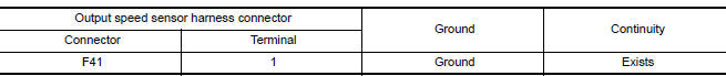
1.CHECK OUTPUT SPEED SENSOR POWER CIRCUIT (CHECK 1)
- Turn ignition switch OFF.
- Disconnect the output speed sensor connector.
- Turn the ignition switch ON.
- Check the voltage between the output speed sensor harness connector and
ground.

Is the check result normal?
YES >> GO TO 2.
NO >> GO TO 6.
2.CHECK OUTPUT SPEED SENSOR GROUND CIRCUIT
- Turn ignition switch OFF.
- Check the continuity between the output speed sensor harness connector
and ground.
Is the check result normal?
YES >> GO TO 3.
NO >> Check or repair the malfunction items.
3.CHECK OUTPUT SPEED SENSOR SIGNAL CIRCUIT (CHECK 1)
- Disconnect the TCM connector.
- Check the continuity between the output speed sensor harness connector
and the TCM harness connector.
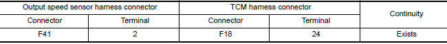
Is the check result normal?
YES >> GO TO 4.
NO >> Check or repair the malfunction items.
4.CHECK OUTPUT SPEED SENSOR SIGNAL CIRCUIT (CHECK 2)
Check the continuity between the output speed sensor harness connector and
ground. 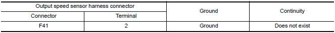
Is the check result normal?
YES >> GO TO 5.
NO >> Check or repair the malfunction items.
5.CHECK OUTPUT SPEED SENSOR SIGNAL
- Connect all of the disconnected connectors.
- Lift the vehicle.
- Start the engine.
- Check the frequency of the output speed sensor.
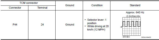
Is the check result normal?
YES >> Perform a simulation test to judge the cause of the malfunction. Refer to GI, "Intermittent Incident".
NO >> Replace the output speed sensor. Refer to TM, "Removal and Installation".
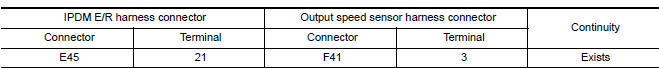
6.CHECK OUTPUT SPEED SENSOR POWER CIRCUIT (CHECK 2)
- Disconnect the IPDM E/R connector.
- Check the continuity between the IPDM E/R harness connector terminal and
the output speed sensor.
Is the check result normal?
YES >> GO TO 7.
NO >> Repair or replace the malfunctioning parts.
7.CHECK OUTPUT SPEED SENSOR POWER CIRCUIT (CHECK 3)
Check the continuity between the IPDM E/R harness connector terminal and
ground. 
Is the check result normal?
YES >> GO TO 8.
NO >> Repair or replace the malfunctioning parts.
8.DETECTION OF MALFUNCTION ITEMS
- Check the following items:
- Harness open circuit or short circuit between the ignition switch and IPDM E/R. Refer to PG, "Wiring Diagram - Ignition Power Supply -".
- 10 A fuse (#49, IPDM E/R). Refer to PG, "IPDM E/R Terminal Arrangement".
- IPDM E/R
Is the check result normal?
YES >> Check intermittent incident. Refer to GI, "Intermittent Incident".
NO >> Repair or replace the malfunctioning parts.
 P0717 Input speed sensor A
DTC Logic DTC DETECTION LOGIC DTC Trouble diagnosis name DTC detection condition Possible causes P0717 Input/Turbine Speed Sensor "A" Circuit No Signal Under the fo ...
P072C Stuck in 1GR
DTC Logic DTC DETECTION LOGIC DTC Trouble diagnosis name DTC detection condition Possible causes P072C Stuck in Gear 1 The following diagnosis conditions are met a ...
Other materials:
How to select piston and bearing
Description
Selection points
Selection parts
Selection items
Selection methods
Between cylinder block and
crankshaft
Main bearing
Main bearing grade (bearing
thickness)
Determined by match of cylinder
block bearing housing
grade (inner diameter of housi ...
U1001 CAN comm circuit
Description
CAN (Controller Area Network) is a serial communication line for real time
application. It is an onvehicle multiplex
communication line with high data communication speed and excellent error
detection ability. Many electronic
control units are equipped onto a vehicle, and each con ...
Categories
- Manuals Home
- Nissan Versa Owners Manual
- Nissan Versa Service Manual
- Video Guides
- Questions & Answers
- External Resources
- Latest Updates
- Most Popular
- Sitemap
- Search the site
- Privacy Policy
- Contact Us

0.0056