Nissan Versa (N17): Passenger side door mirror defogger
Description
Heats the heating wire with the power supply from the rear window defogger relay to prevent the door mirror from fogging up.
Component Function Check
1.CHECK DOOR MIRROR DEFOGGER RH
Check that the heating wire of door mirror defogger RH is heated when turning the rear window defogger switch ON.
Is the inspection result normal?
YES >> Door mirror defogger RH is OK.
NO >> Refer to DEF "Diagnosis Procedure".
Diagnosis Procedure
Regarding Wiring Diagram information, refer to DEF "Wiring Diagram".
1. CHECK POWER SUPPLY CIRCUIT
1. Turn ignition switch OFF.
2. Disconnect door mirror RH.
3. Turn ignition switch ON.
4. Check voltage between door mirror RH connector and ground.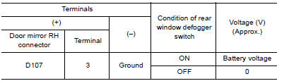
Is the inspection result normal?
YES >> GO TO 2
NO >> Repair or replace harness.
2. CHECK GROUND CIRCUIT
1. Turn ignition switch OFF.
2. Check continuity between door mirror RH connector and ground.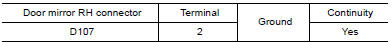
Is the inspection result normal?
YES >> GO TO 3
NO >> Repair or replace harness.
3. CHECK PASSENGER SIDE DOOR MIRROR DEFOGGER
Check door mirror defogger RH. Refer to DEF "Component Inspection".
Is the inspection result normal?
YES >> GO TO 4
NO >> Replace door mirror RH. Refer to MIR "DOOR MIRROR ASSEMBLY : Removal and Installation".
4. CHECK INTERMITTENT INCIDENT
Check intermittent incident.
Refer to GI "Intermittent Incident".
Is the inspection result normal?
YES >> Check the following.
- Battery power supply circuit.
- Fuse block (J/B).
NO >> Repair or replace the malfunctioning parts.
Component Inspection
1. CHECK DOOR MIRROR DEFOGGER RH
1. Turn ignition switch OFF.
2. Disconnect door mirror RH.
3. Check continuity between door mirror terminals.

Is the inspection result normal?
YES >> Inspection End.
NO >> Replace door mirror RH. Refer to MIR "DOOR MIRROR ASSEMBLY : Removal and Installation".
SYMPTOM DIAGNOSIS
 Driver side door mirror defogger
Description Heats the heating wire with the power supply from the rear window defogger relay to prevent the door mirror from fogging up. ...
Rear window defogger and door
mirror defogger do not operate
Diagnosis Procedure 1. CHECK REAR WINDOW DEFOGGER SWITCH Check rear window defogger switch. Refer to DEF "Component Function Check". Is the inspection result normal? YES >> GO ...
Other materials:
Heater and Air Conditioner (manual)
WARNING
The air conditioner cooling function operates
only when the engine is running.
Do not leave children or adults who
would normally require the assistance
of others alone in your vehicle. Pets
should also not be left alone. They
could accidentally injure themselves or
others ...
Cold weather driving
Freeing a frozen door lock
To prevent a door lock from freezing, apply deicer
through the key hole. If the lock becomes
frozen, heat the key before inserting it into the key
hole, or use the remote keyless entry key fob or
the NISSAN Intelligent Key.
Antifreeze
In the winter when it is antic ...
Categories
- Manuals Home
- Nissan Versa Owners Manual
- Nissan Versa Service Manual
- Video Guides
- Questions & Answers
- External Resources
- Latest Updates
- Most Popular
- Sitemap
- Search the site
- Privacy Policy
- Contact Us

0.0059