Nissan Versa (N17): Component parts
Component Parts Location
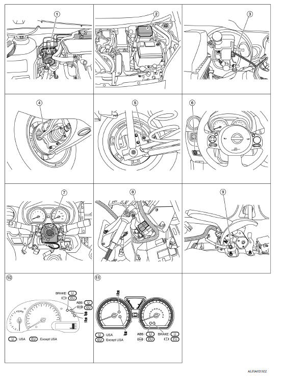
1 ABS actuator and electric unit (control unit) 2 IPDM E/R 3 Brake fluid level switch (view with IPDM E/R removed) 4 Front wheel sensor 5 Rear wheel sensor 6 VDC OFF switch 7 Steering angle sensor (view with steering wheel and spiral cable removed) 8 Stop lamp switch 9 Parking brake switch (view with console removed) 10 Combination meter (type A) 11 Combination meter (type B)
Component Description
| Component | Reference/Function |
| ABS actuator and electric unit (control unit) | BRC "ABS Actuator and Electric Unit (Control Unit)" |
| Wheel sensor | BRC "Wheel Sensor and Sensor Rotor" |
| Stop lamp switch | BRC "Stop Lamp Switch" |
| Steering angle sensor | BRC "Steering Angle Sensor" |
| VDC OFF switch | BRC "VDC OFF Switch" |
| Brake fluid level switch | BRC "Brake Fluid Level Switch" |
| Parking brake switch | BRC "Parking Brake Switch" |
| ABS warning lamp | BRC "VDC/TCS/ABS : System Description" |
| Brake warning lamp | |
| VDC OFF indicator lamp | |
| SLIP indicator lamp | |
| ECM | Transmits the following signals to ABS actuator and electric unit
(control unit) via CAN
communication. - Accelerator pedal position signal - Engine speed signal - Target throttle position signal |
| TCM | Transmits the current gear position signal to ABS actuator and electric unit (control unit) via CAN communication. |
ABS Actuator and Electric Unit (Control Unit)
Electric unit (control unit) is integrated with actuator and comprehensively controls VDC function, TCS function, ABS function and EBD function.
ELECTRIC UNIT (CONTROL UNIT)
- Brake fluid pressure is controlled according to signals from each sensor.
- If malfunction is detected, the system enters fail-safe mode.
ACTUATOR
The following components are integrated with ABS actuator.
Pump
Returns the brake fluid reserved in reservoir to master cylinder by reducing pressure.
Motor
Activates the pump according to signals from ABS actuator and electric unit (control unit).
Motor Relay
Operates the motor ON/OFF according to signals from ABS actuator and electric unit (control unit).
Actuator Relay (Main Relay)
Operates each valve ON/OFF according to signals from ABS actuator and electric unit (control unit).
ABS IN Valve
Switches the fluid pressure line to increase or hold according to signals from control unit.
ABS OUT Valve
Switches the fluid pressure line to increase, hold or decrease according to signals from control unit.
Cut Valve 1, Cut Valve 2
Shuts off the ordinary brake line from master cylinder, when VDC function and TCS function are activated.
Suction Valve 1, Suction Valve 2
Supplies the brake fluid from master cylinder to the pump, when VDC function and TCS function are activated.
Return Check Valve
Returns the brake fluid from brake caliper and wheel cylinder to master cylinder by bypassing orifice of each valve when brake is released.
Reservoir
Temporarily reserves the brake fluid drained from brake caliper, so that pressure efficiently decreases when decreasing pressure of brake caliper and wheel cylinder.
Yaw rate/side/decel G sensor
Calculates the following information that affects the vehicle, and transmits a signal to ABS actuator and electric unit (control unit) via communication lines.
- Vehicle rotation angular velocity (yaw rate signal)
- Vehicle lateral acceleration (side G signal) and longitudinal acceleration (decel G signal)
Pressure Sensor
Detects the brake fluid pressure and transmits signal to ABS actuator and electric unit (control unit).
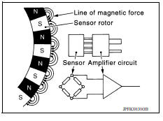
Wheel Sensor and Sensor Rotor
NOTE:
- Wheel sensor of front wheel is installed on steering knuckle.
- Sensor rotor of front wheel is integrated in wheel hub assembly.
- Wheel sensor of rear wheel is installed on back plate of rear brake.
- Sensor rotor of rear wheel is installed on rear brake drum.
- Never measure resistance and voltage value using a tester because sensor is active sensor.
- Downsize and weight reduction is aimed. IC for detection portion and magnet for sensor rotor are adopted.
- Power supply is supplied to detection portion so that magnetic field line is read. Magnetic field that is detected is converted to current signal.
- When sensor rotor rotates, magnetic field changes. Magnetic field change is converted to current signals (rectangular wave) and is transmitted to ABS actuator and electric unit (control unit). Change of magnetic field is proportional to wheel speed.
Stop Lamp Switch
Detects the operation status of brake pedal and transmits converted electric signal to ABS actuator and electric unit (control unit).
Steering Angle Sensor
Detects the following information and transmits steering angle signal to ABS actuator and electric unit (control unit) via CAN communication.
- Steering wheel rotation amount
- Steering wheel rotation angular velocity
- Steering wheel rotation direction
VDC OFF Switch
- Non-operational status or standby status of VDC and TCS functions can be
selected using VDC OFF switch.
VDC OFF indicator lamp indicates the operation status of function. (ON: Non-operational status, OFF: Standby status)
- VDC OFF indicator lamp turns OFF (standby status) when the engine is started again after it is stopped once while VDC OFF indicator lamp is ON (non-operational status).
Brake Fluid Level Switch
Detects the brake fluid level in reservoir tank and transmits converted electric signal from combination meter to ABS actuator and electric unit (control unit) via CAN communication.
Parking Brake Switch
Detects the operation status of parking brake switch and transmits converted electric signal from combination meter to ABS actuator and electric unit (control unit) via CAN communication.
SYSTEM
 Precautions
VDC/TCS/ABS
VDC/TCS/ABS : System Diagram ...
Other materials:
Windows
Power windows (if so equipped)
WARNING
Make sure that all passengers have
their hands, etc. inside the vehicle while
it is in motion and before closing the
windows. Use the window lock switch to
prevent unexpected use of the power
windows
To help avoid risk of injury or death
thr ...
Line pressure test
Work Procedure
INSPECTION
Inspect the amount of engine oil. Replenish the engine oil if necessary.
Refer to LU, "Inspection".
Drive for about 10 minutes to warm up the vehicle so that the A/T fluid
temperature is to 50 to 80C (122
to 176F).
Inspect the amount of ATF. Rep ...
Categories
- Manuals Home
- Nissan Versa Owners Manual
- Nissan Versa Service Manual
- Video Guides
- Questions & Answers
- External Resources
- Latest Updates
- Most Popular
- Sitemap
- Search the site
- Privacy Policy
- Contact Us

0.0069